Variable nozzle unit and variable-geometry turbocharger

a variable-geometry, nozzle unit technology, applied in the direction of machines/engines, mechanical apparatus, liquid fuel engines, etc., can solve the problem of high difficulty in and achieve the effect of improving the turbine efficiency of the variable-geometry turbocharger and sufficiently preventing the leakage of exhaust gas through the end gaps of multiple seal rings

Active Publication Date: 2015-02-26
IHI CORP
View PDF8 Cites 22 Cited by
  • Summary
  • Abstract
  • Description
  • Claims
  • Application Information

AI Technical Summary

Benefits of technology

[0016]According to the present invention, the leakage of the exhaust gas via the end gaps of the multiple seal rings can be sufficiently prevented

Problems solved by technology

For this reason, there is a problem of a difficulty in improving turb

Method used


Image

  • Variable nozzle unit and variable-geometry turbocharger
  • Variable nozzle unit and variable-geometry turbocharger
  • Variable nozzle unit and variable-geometry turbocharger

Examples


modified example

[0050]A modified example of the embodiment of the present invention will be described with reference to FIG. 5A and FIG. 5B. In the drawings, “R” indicates rightward while “L” indicates leftward.

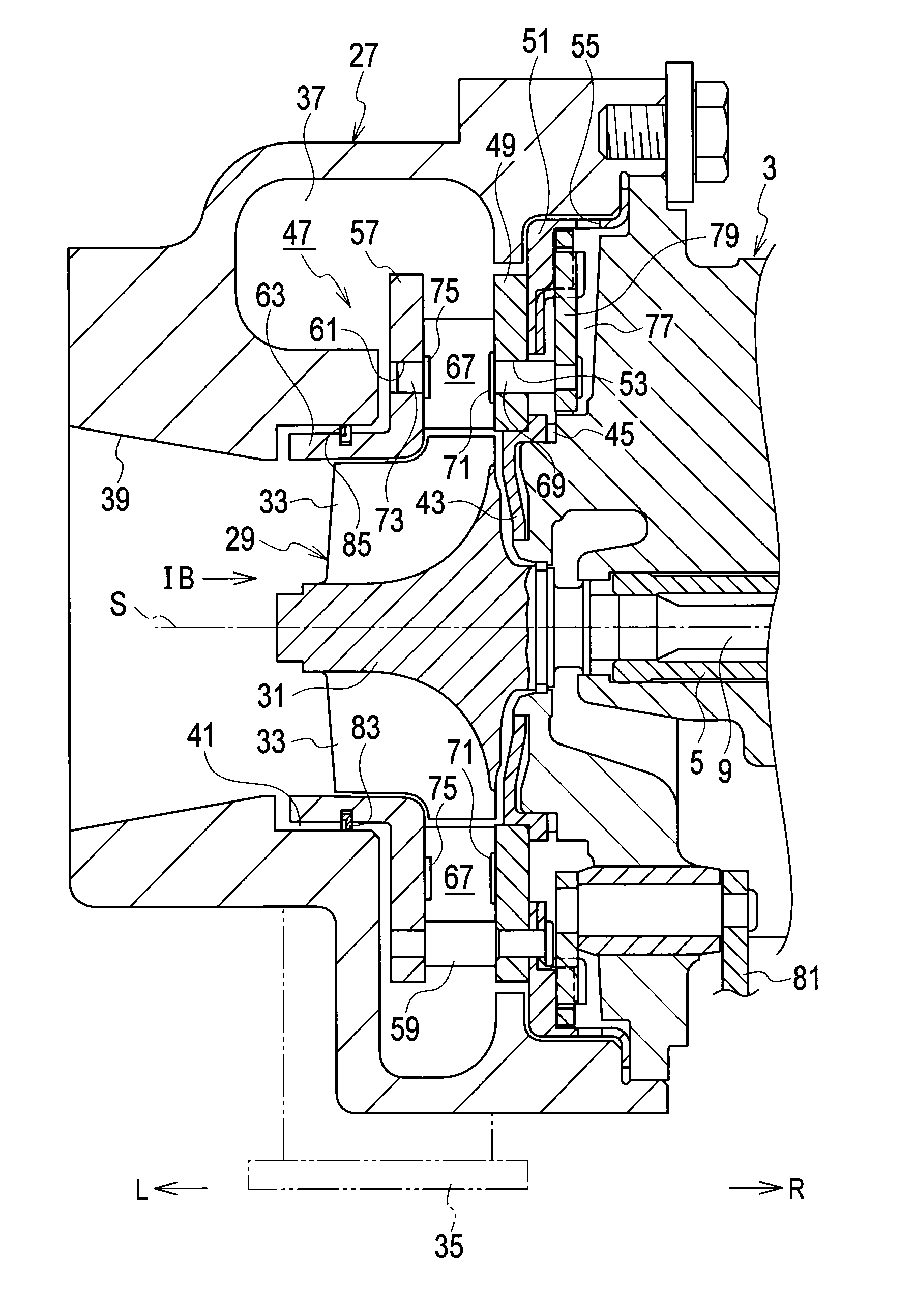
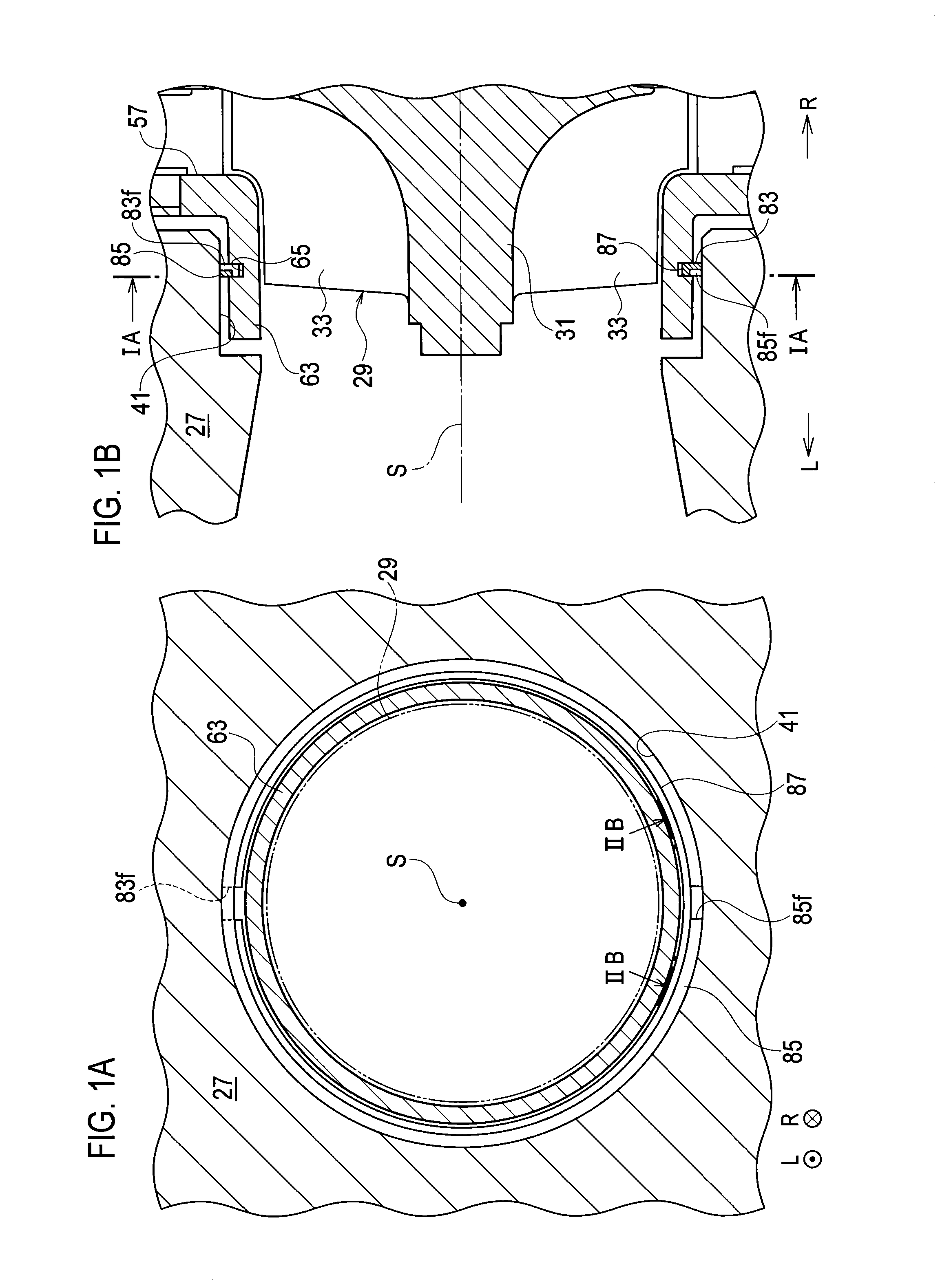
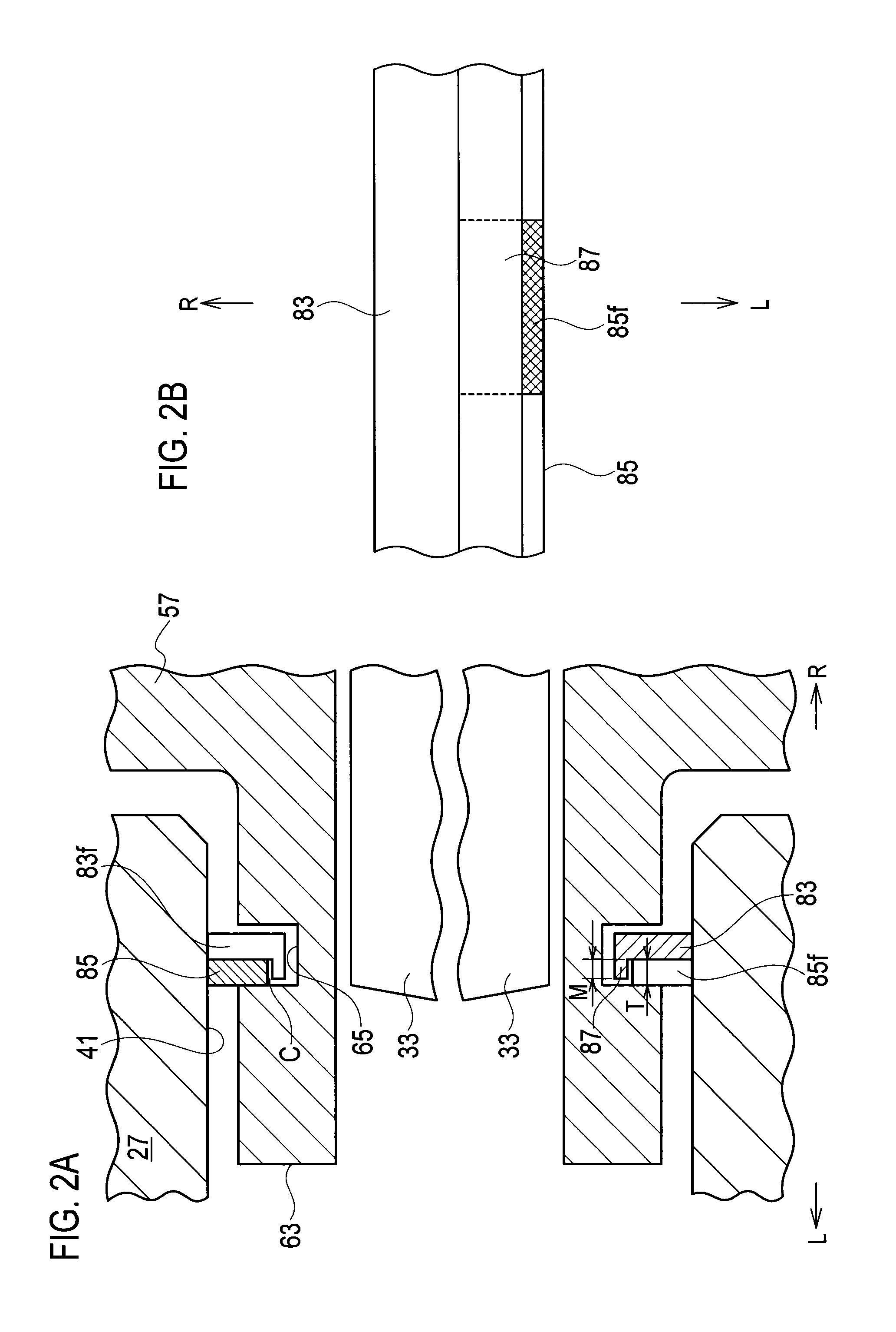
[0051]The variable nozzle unit 47 may use three (multiple) seal rings 89, 91, and 93 (the most upstream-side seal ring 89, the intermediate seal ring 91, and the most downstream-side seal ring 93) as shown in FIG. 5A and FIG. 5B instead of using the two seal rings 83 and 85 (see FIG. 1B and FIG. 2A). In this case, a circumferential position of an end gap 89f of the most upstream-side seal ring 89, a circumferential position of an end gap (not shown) of the intermediate seal ring 91, and a circumferential position of an end gap 93f of the most downstream-side seal ring 93 are displaced from one another. Meanwhile, an annular seal flange 95 is formed at an inner peripheral edge portion of either the intermediate seal ring 91 or the most upstream-side seal ring 93. Thus, when the multiple seal ...


PUM


Abstract

An annular seal flange is formed at an inner peripheral edge portion of an upstream-side seal ring. The seal flange projects in a downstream direction. When seal rings are viewed from radially inside, the seal flange of the upstream-side seal ring is designed to at least partially occlude an end gap of the downstream-side (the most downstream-side) seal ring.

Description

CROSS REFERENCE TO RELATED APPLICATIONS[0001]This application is a continuation application of International Application No. PCT / JP2013 / 064589, filed on May 27, 2013, which claims priority to Japanese Patent Application No. 2012-121972, filed on May 29, 2012, the entire contents of which are incorporated by references herein.BACKGROUND OF THE INVENTION[0002]1. Field of the Invention[0003]The present invention relates to a variable nozzle unit which can change a passage area for (a flow rate of) an exhaust gas to be supplied to a turbine impeller side in a variable-geometry turbocharger, and the like.[0004]2. Description of the Related Art[0005]A typical variable nozzle unit used in a variable-geometry turbocharger is disposed between a turbine scroll passage and a gas discharge port inside a turbine housing in such a way as to surround a turbine impeller. A specific configuration of such a typical variable nozzle unit (a conventional variable nozzle unit) is as follows (see Japanese...

Claims


Application Information

Patent Timeline
IPC IPC(8): F04D27/00F04D29/12
CPCF04D29/122F04D27/002F02B37/24F01D11/005F01D17/165F05D2220/40F05D2250/75F05D2240/58F05D2240/581
Inventor SEGAWA, KENICHI
Owner IHI CORP
Why Eureka
Try Eureka