Ball Net Structure

a technology for nets and balls, applied in tennis, racket sports, sport apparatus, etc., can solve the problems of inability to stretch and tighten the net, lack of elastic metal, and inability to function well, and achieve the effect of high rigidity

Inactive Publication Date: 2015-02-26
CHEN BENJAMIN
View PDF10 Cites 10 Cited by
  • Summary
  • Abstract
  • Description
  • Claims
  • Application Information

AI Technical Summary

Benefits of technology

[0007]It is an objective of the present invention to provide a ball net structure characterized by an optimal ratio of rigid metallic pipe to flexible resilient rod by length, such that the high-flexibility resilient rods not only bend to attain optimal curvature but also produce the largest and evenest tensile force. The ball net structure of the present invention is further characterized by two high-rigidity net-clamping shells which clamp a plastic sheet edge-binder and a first edge or a second edge of the net body and are fixed in place with at least two nails to thereby achieve uniform distribution of stress, allow the net body to bear a relatively large stress, and extend the service life of the net body.
[0008]In order to achieve the above and other objectives, the present invention provides a ball net structure, comprising: a base; two tilted metallic pipes flanking the base and having front ends receiving two resilient rods, respectively, with a 2:1 ratio of metallic pipe to resilient rod by length approximately, such that resilient rods bend to attain optimal curvature and produce the evenest and largest tensile force, and thus a net body is evenly stretched by and between the resilient rods to keep being flat and tight under a uniform outward tensile force.
[0009]In order to achieve the above and other objectives, the present invention provides a ball net structure, comprising: a net body having a first edge and a second edge, wherein a plastic sheet edge-binder is disposed at each of the four edges of the net body; clamping elements for clamping the first edge and the second edge; a net-clamping shell of high rigidity for clamping the two clamping elements, the plastic sheet edge-binder, and the first or second edge of the net body, wherein at least two nails are disposed on each of the net-clamping shells, spaced apart, and adapted to fix the net-clamping shells in place, such that the at least two nails enable the two clamping elements, the plastic sheet edge-binder, and the first or second edge of the net body to bear any force jointly and equally and thus incur uniform distribution, rather than concentration, of stress, thereby extending the service life of the net body.

Problems solved by technology

However, metal lacks elasticity, and thus it is impossible to stretch and tighten the net.
As a result, the net is so flaccid that it does not function well but becomes boring to the players, thereby causing the players to reduce sport duration or frequency eventually.
Furthermore, a structure made of steel or iron is not only heavy but also incapable of bending; hence, to be bent to attain a curvature, it must be processed, though processing it to attain a curvature is no easy job.
According to the prior art, although a conventional net body is peripherally provided with a plastic sheet edge-binder, the plastic sheet edge-binder is subjected directly to a tensile force, and the plastic sheet is too thin to bear a large tensile force.
Furthermore, the tensile force is concentrated at the top and bottom of the two edges of the plastic sheet edge-binder; as a result, the top and bottom of the two edges of the plastic sheet edge-binder are susceptible to damage.
Accordingly, the conventional net body is susceptible to damage and has a short service life.
Furthermore, it is inconvenient and takes time to erect and store the conventional net body; as a result, sports which require the conventional net body are relatively unpopular because of the aforesaid drawbacks of the conventional net body.

Method used


Image

  • Ball Net Structure
  • Ball Net Structure
  • Ball Net Structure

Examples


Embodiment Construction

[0025]The present invention provides a ball net structure.

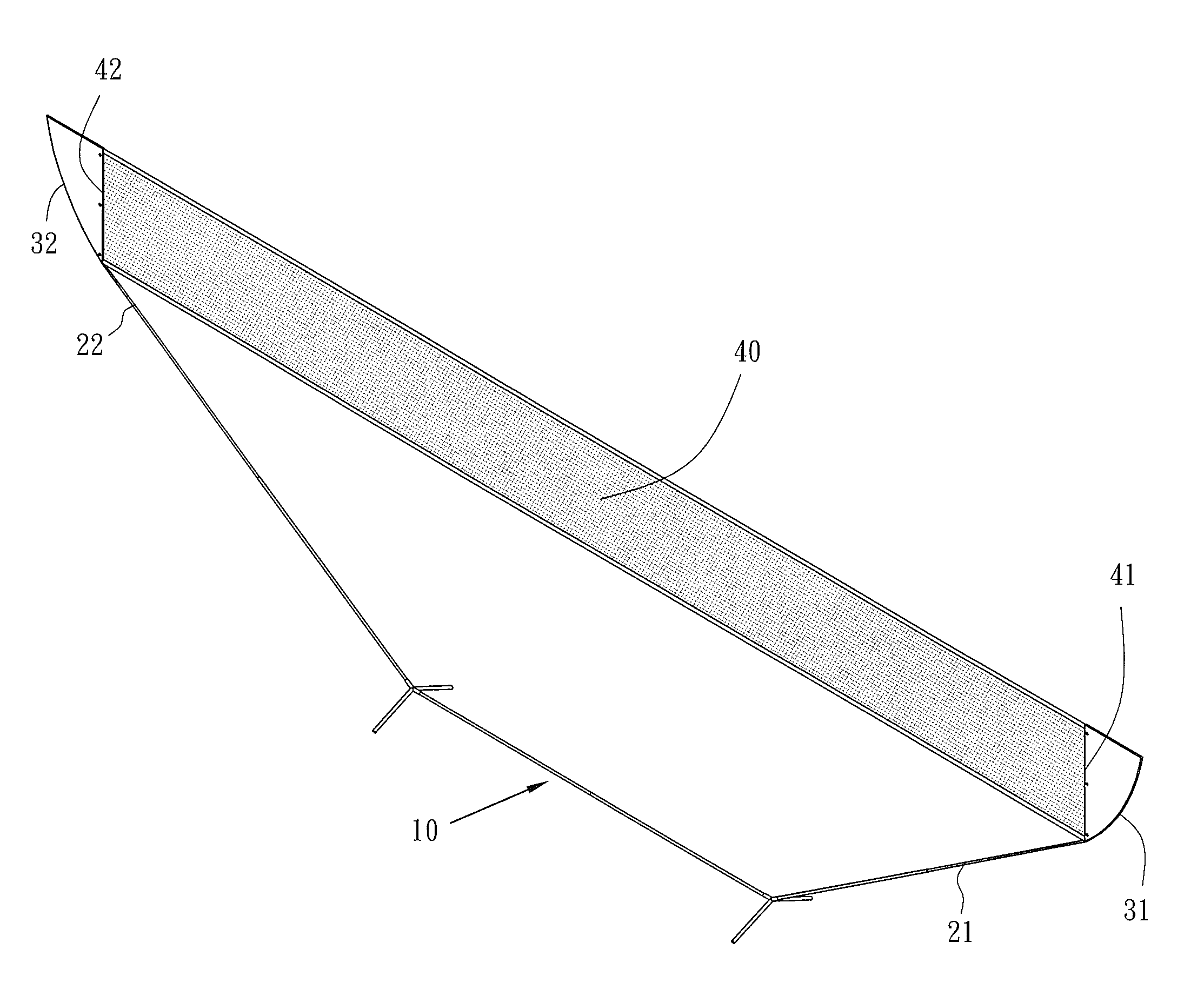
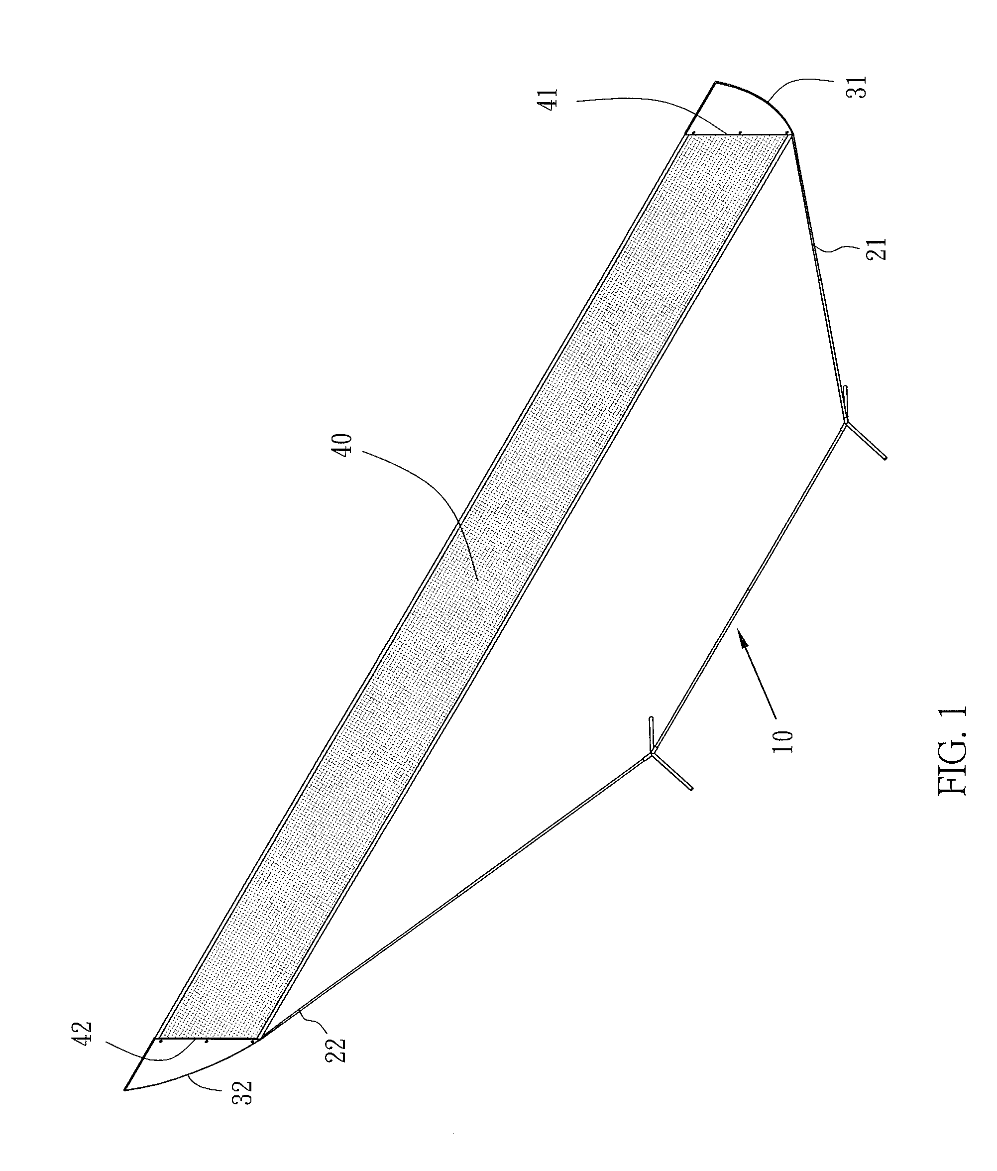
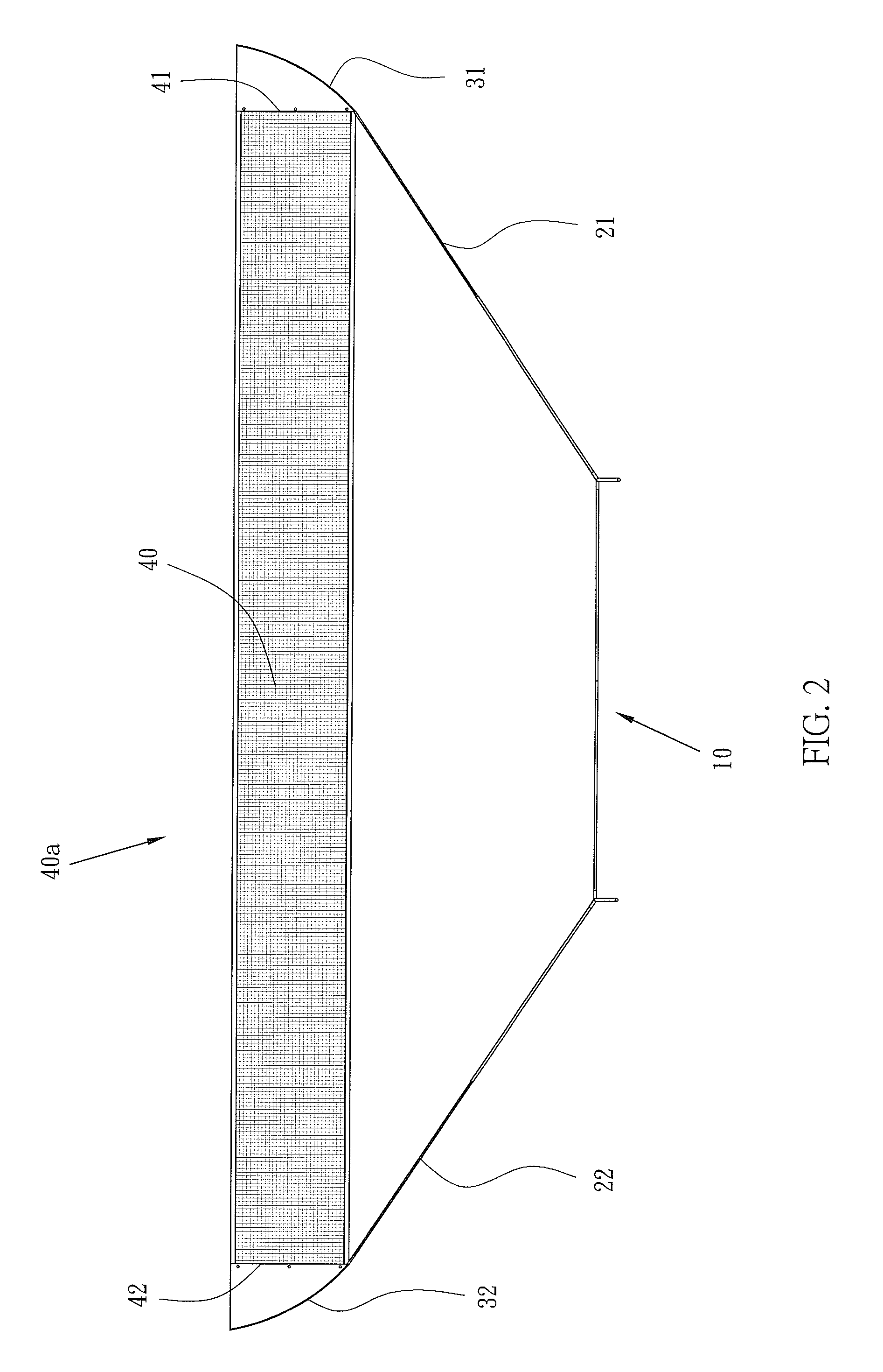
[0026]Referring to FIG. 1 through FIG. 3, the present invention provides a ball net structure which comprises a base 10, two tilted metallic pipes 21, 22, two resilient rods 31, 32, and a net body 40.

[0027]The base 10 is disposed on the ground.

[0028]The two tilted metallic pipes 21, 22 are insertedly disposed on two sides of the base 10 and titled outward.

[0029]The two resilient rods 31, 32 have insertion ends 311, 321, respectively. The insertion ends 311, 321 are inserted into the tilted metallic pipes 21, 22, respectively, and fixed in place. The tilted metallic pipes 21, 22 are longer than the resilient rods 31, 32 which are made from spherical fiber or carbon fiber, such that the resilient rods 31, 32 can bend in a manner to have optimal curvature and produce the evenest and largest tensile force.

[0030]In the embodiments of the present invention, the net body 40 comes in the form of a volleyball net body 40b, badminton n...


PUM


Abstract

A ball net structure includes: a base; two tilted metallic pipes flanking the base and having front ends receiving two resilient rods, respectively, wherein the tilted metallic pipes are longer than the resilient rods, allowing the resilient rods to bend and achieve optimal curvature and produce the evenest and largest tensile force; a net body stretched by and between the resilient rods to keep being flat and tight; a plastic sheet edge-binder disposed at each of four edges of the net body; clamping elements for clamping first and second edges of the net body; two net-clamping shells for clamping the clamping elements, the plastic sheet edge-binder, and the first and second edges of the net body, wherein at least two nails are disposed on each of the net-clamping shells to fix the net-clamping shells in place, achieving uniform distribution of stress and extending the service life of the net body.

Description

BACKGROUND OF THE INVENTION[0001]1. Technical Field[0002]The present invention relates to nets for ball games, and more particularly, to a ball net structure characterized by an optimal ratio of rigid metallic pipe to flexible resilient rod by length, allowing the resilient rod to bend to attain optimal curvature and produce the largest and evenest tensile force, and characterized in that two high-rigidity net-clamping shells clamp a plastic sheet edge-binder and a first edge or a second edge of the net body and are fixed in place with at least two nails to spread stress uniformly, enable a net body to bear greater stress, and extend the service life of the ball net structure.[0003]2. Description of Related Art[0004]Conventional ball games, such as tennis, volleyball, beach volleyball, and badminton, require a net for separating the two opposing players or teams. According to the prior art, a net fastening process entails erecting two metallic bars on two edges of a net and then fas...

Claims


Application Information

Patent Timeline
Patent Type & Authority Applications(United States)
IPC IPC(8): A63B61/02A63B69/00A63B63/00A63B61/00
CPCA63B61/02A63B61/003A63B69/0002A63B2210/50A63B2243/0095A63B2243/0087A63B2243/0083A63B63/004A63B2063/005A63B2071/024A63B2102/02A63B2102/04A63B2209/02A63B2209/10
Inventor CHEN, BENJAMIN
Owner CHEN BENJAMIN
Why Eureka
Try Eureka