

Flow-control valve system and method
- Summary
- Abstract
- Description
- Claims
- Application Information
AI Technical Summary
Benefits of technology
Problems solved by technology
Method used
Image

Examples
Embodiment Construction
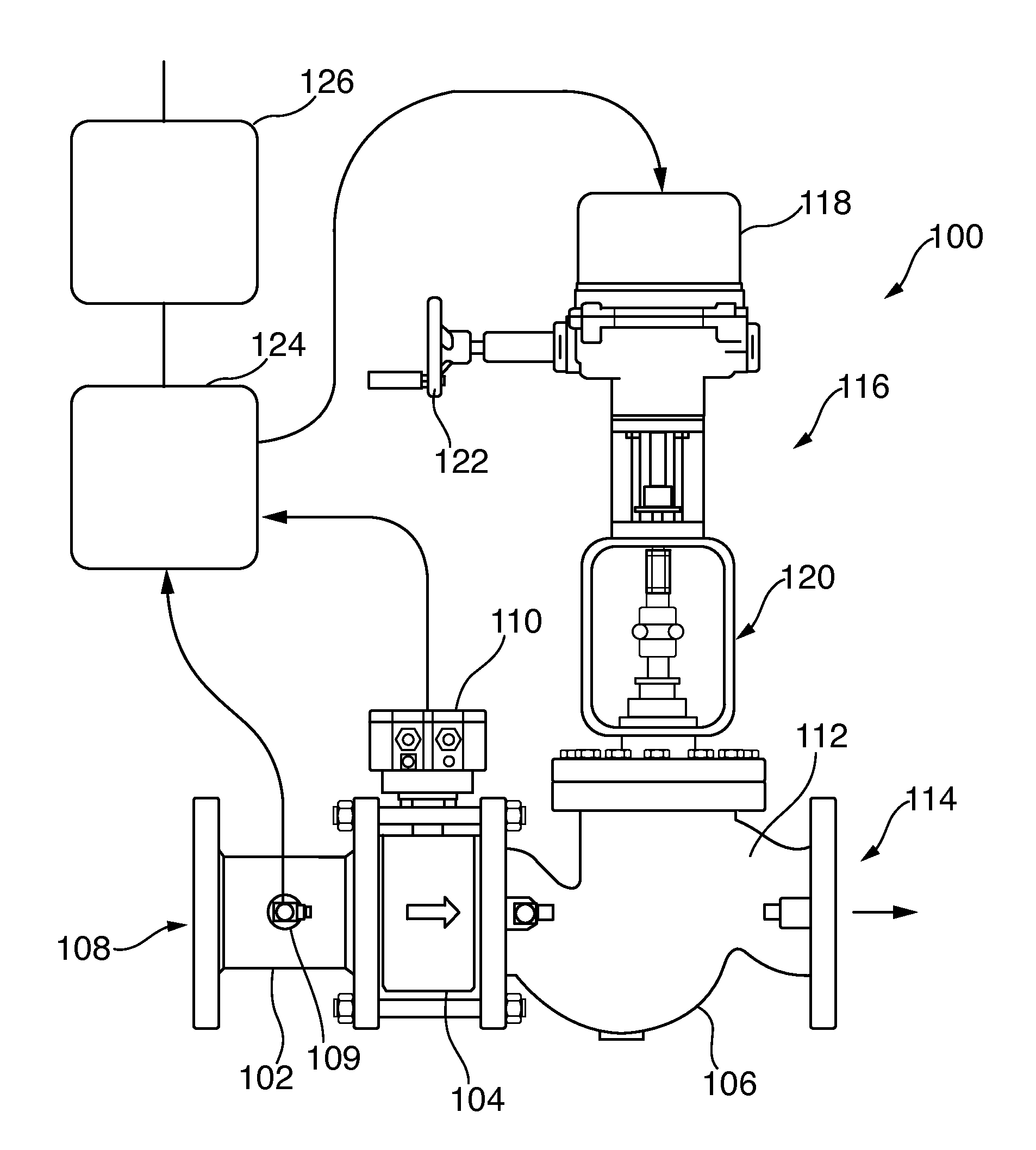
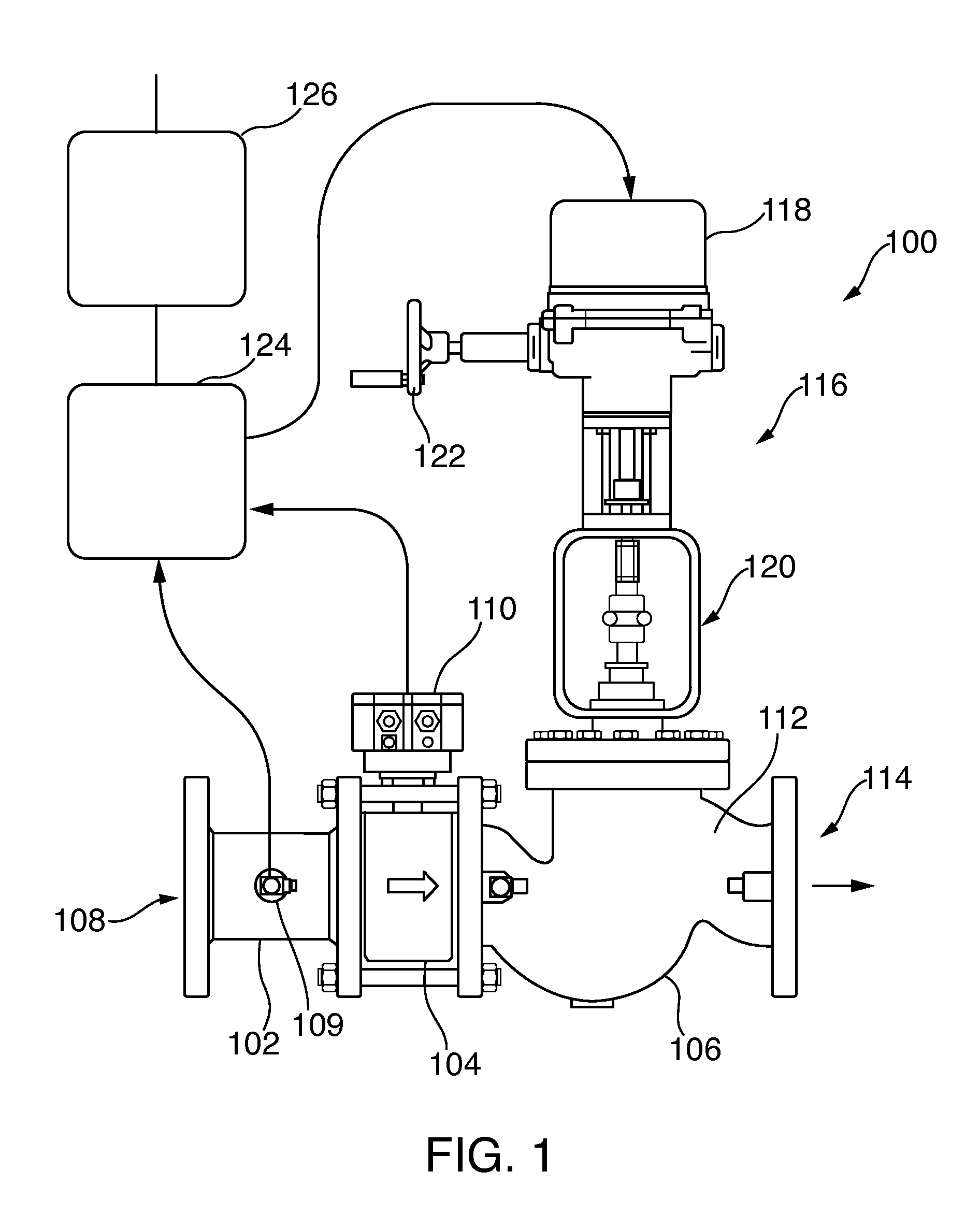
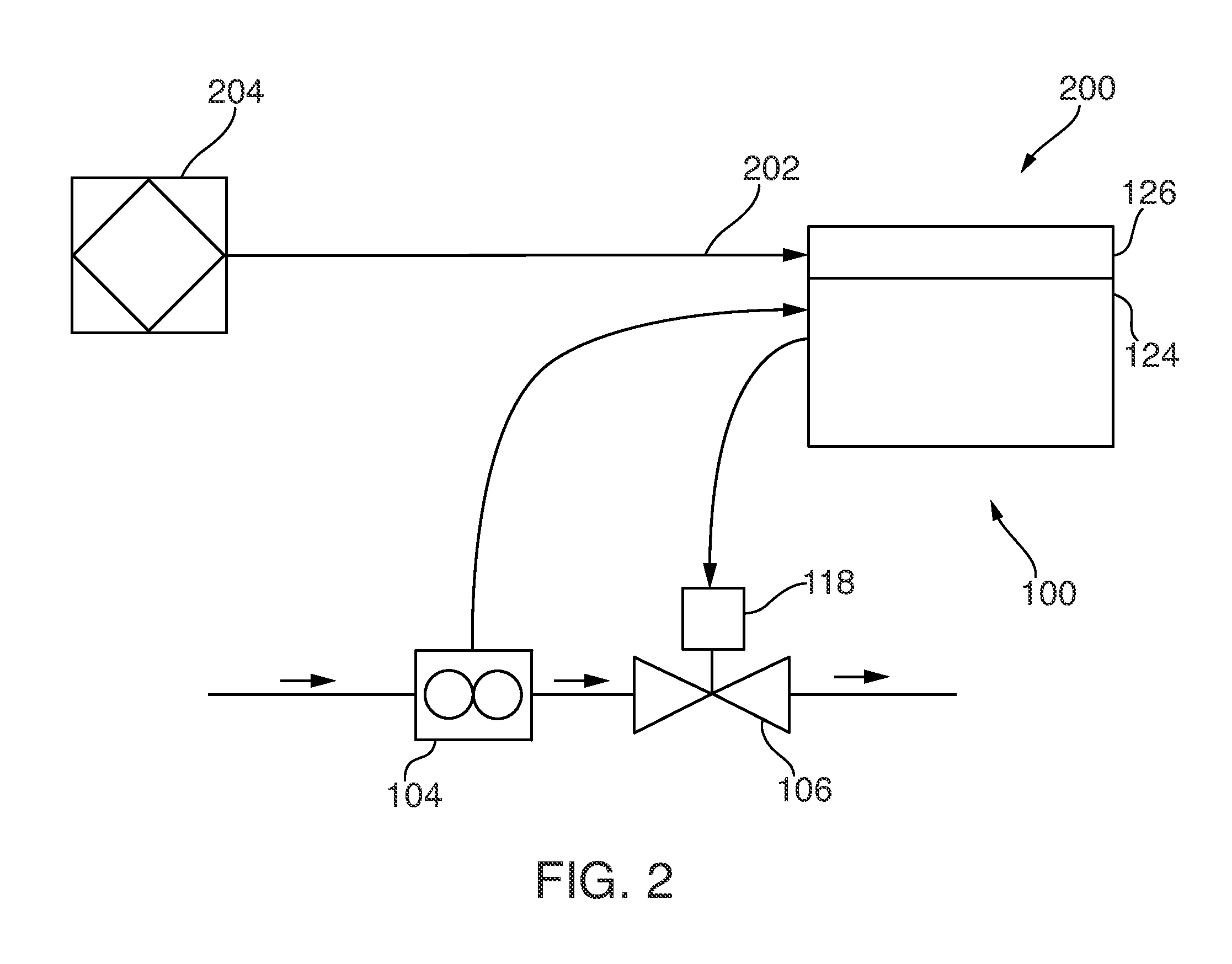
[0019]This disclosure relates to flow control in fluid systems and, more particularly, to a flow control system that can selectively control the flow of fluid through a conduit irrespective of system pressure fluctuations and particular flow characteristics of the system. In one disclosed embodiment, a flow metering control valve (FMCV) system is disclosed. The FMCV operates as a fluid control valve that is pressure-independent and that uses electronic software control algorithms to model the behavior of a conventional mechanical pressure-independent control valve (PICV) in a system. By using electronic controls operating a valve based on a flow model, the FMCV is advantageously fully customizable to each application, flexible in its operation, and responsive to rapidly changing flow commands. Moreover, certain described FMCV embodiments are configured to provide feedback and system operating information such as flow saturation, in real time, which enables quick system response and ...
PUM
 Abstract
Description
Claims
Application Information