
Power Distribution Method for Electric Vehicle Driven by Two Power Sources

a technology of power distribution and electric vehicles, applied in vehicle position/course/altitude control, process and machine control, instruments, etc., can solve the problems of tire drivers, low transmission efficiency of continuously variable transmissions, and inconvenient use of drivers, so as to increase the operation efficiency of electric vehicles.

Inactive Publication Date: 2015-02-26
NAT PINGTUNG UNIV OF SCI & TECH
View PDF12 Cites 34 Cited by
  • Summary
  • Abstract
  • Description
  • Claims
  • Application Information

AI Technical Summary

Benefits of technology

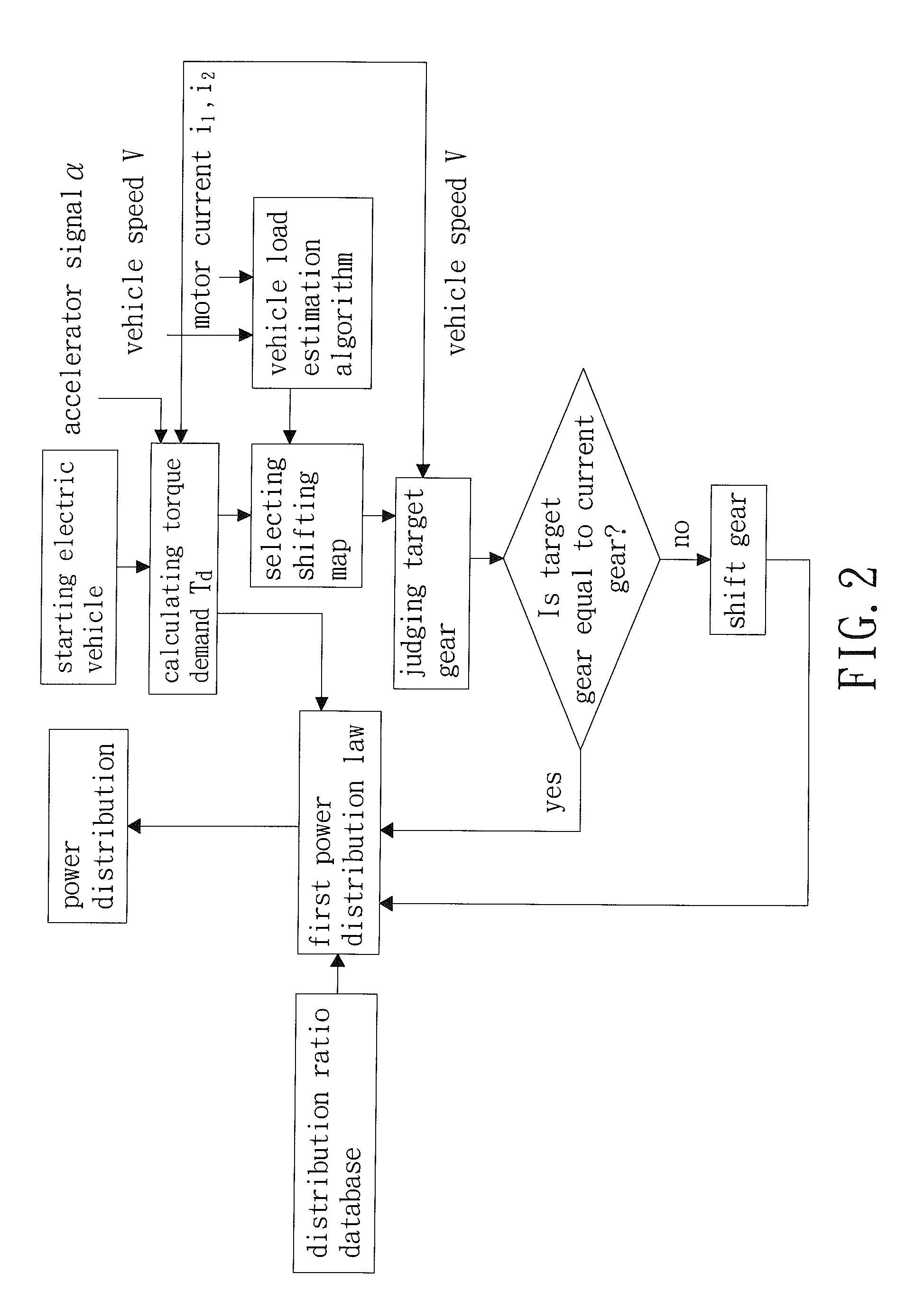
The present invention provides a power distribution method for an electric vehicle driven by two power sources. The method uses a vehicle control unit to calculate a distribution ratio based on vehicle speed, torque demand, and current gear of a transmission. The powers outputted by the two motors are adjusted accordingly to increase operational efficiency. Additionally, the vehicle control unit uses a vehicle load estimation algorithm to select the optimal gear for the second motor, reducing energy consumption and improving operational convenience. Furthermore, the power is distributed according to a second power distribution law before gear shifting of the transmission to ensure smooth power output during gear shifting and to shorten the time required for gear shifting to increase driving comfort.

Problems solved by technology

Conforming to this trend the electric vehicle industry develops flourishingly, but thus, many technical problems occurred.
Continuously variable transmissions have low transmission efficiency due to slips during gear shifting processes.
Manual transmissions having the highest transmission efficiency but tire the drivers and are inconvenient in use.
However, automated manual transmissions are expensive and, when a limited number of gears are provided, may result in uncomfortable feel to the drivers due to torque holes during gear shifting processes.

Method used


Image

  • Power Distribution Method for Electric Vehicle Driven by Two Power Sources
  • Power Distribution Method for Electric Vehicle Driven by Two Power Sources
  • Power Distribution Method for Electric Vehicle Driven by Two Power Sources

Examples


Embodiment Construction

[0059]A power distribution method according to the present invention can be

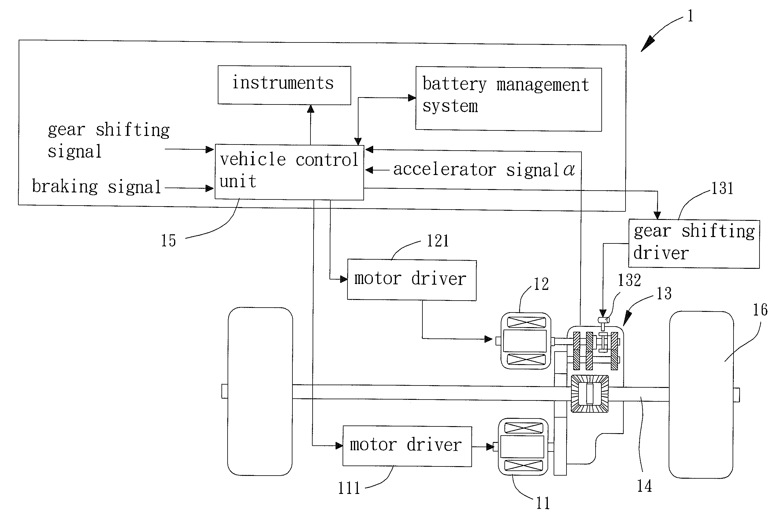
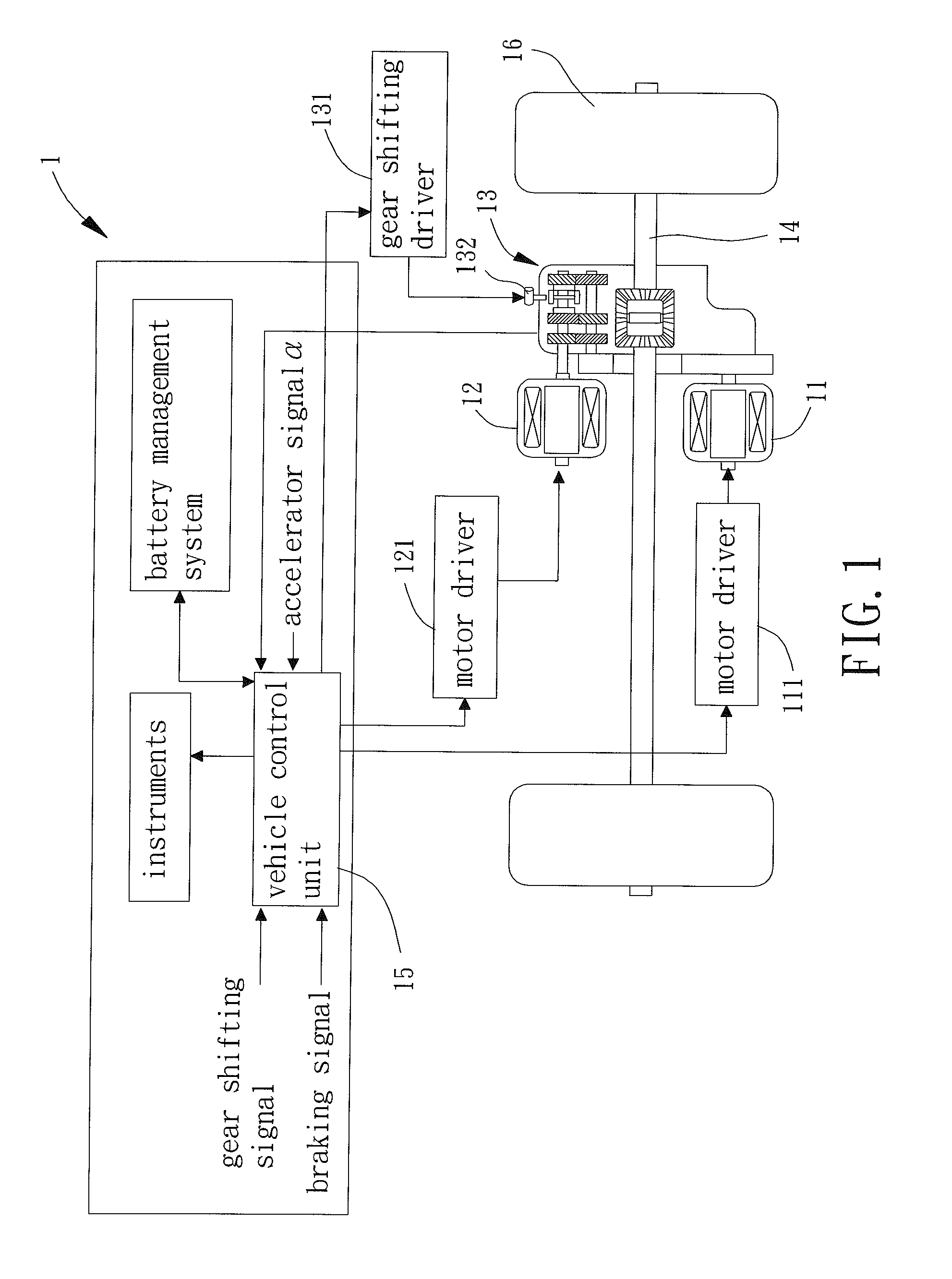
[0060]A power distribution method according to the present invention can be used on the electric vehicle 1 driven by two power sources shown in FIG. 1. The electric vehicle 1 is driven by first and second motors 1 and 2. The second motor 12 is connected to a transmission 13 such as an automatic transmission. In this embodiment, the transmission 13 is a clutchless automatic transmission having a first gear G1, a second gear G2, and a third gear G3. However, other forms of transmissions can be used. Furthermore, the power distribution method can be used on hybrid vehicles or other forms of electric vehicles driven by two power sources.

[0061]FIG. 2 is a flowchart illustrating an example of the power distribution method for an electric vehicle driven by two power sources according to the present invention. After the electric vehicle 1 is started and enters a driving mode, a vehicle control unit 15 drives the firs...


PUM


Abstract

A power distribution method for electric vehicle driven by two power sources includes executing a first power distribution law by a vehicle control unit, wherein the first power distribution law sets a distribution ratio according to a vehicle speed of the electric vehicle, a torque demand, and a current gear of a transmission. The powers outputted by first and second motors are adjusted according to the distribution ratio such that the first and second motors can operate at the most efficient operation points to increase the operational efficiency of the electric vehicle driven by two power sources.

Description

BACKGROUND OF THE INVENTION[0001]1. Field of the Invention[0002]The present invention relates to a driving method for an electric vehicle and, more particularly, to a power distribution method for an electric vehicle driven by two power sources.[0003]2. Description of the Related Art[0004]Vehicles in the current market used to consume fuels as the main power source. Responsive to the global oil shortage, extensive researches in substitute energy vehicles and hybrid vehicles have been made in industries with an intention to minimize the adverse effect of the oil shortage on the vehicle markets. Every car company actively tried to replace oil with electricity as the power sources for vehicles and developed various electric vehicles and various hybrid vehicles to gradually get rid of reliance of oil, and electricity has been a successful power source and gains a role in the market.[0005]Conforming to this trend the electric vehicle industry develops flourishingly, but thus, many techni...

Claims


Application Information

Patent Timeline
IPC IPC(8): B60W30/188B60W10/10B60W10/08
CPCB60W30/188B60W10/10B60W10/08B60W30/19B60W2520/10B60W2540/10B60W2710/083B60W2710/1005B60K1/02
Inventor TSENG, CHYUAN-YOWTANG, HAN-WEILI, BO-PENG
Owner NAT PINGTUNG UNIV OF SCI & TECH
Learn More