Atomizing Head

a technology of atomizing head and atomizer, which is applied in the direction of tobacco, lighting and heating apparatus, heating types, etc., can solve the problems of difficult control, limited heat generated per unit time by the atomizing head b>300/b>, and negatively affect the enjoyment of smoking electronic cigarettes by users, etc., to achieve easy control, improve liquid flow and airflow, and inhibit dry combustion

Active Publication Date: 2015-03-05
JOYETECH CHANGZHOU ELECTRONICS
View PDF27 Cites 132 Cited by
  • Summary
  • Abstract
  • Description
  • Claims
  • Application Information

AI Technical Summary

Benefits of technology

[0012]One of the purposes of the present invention is to provide an atomizing head assembly that has a simple structure with an improved liquid flow and airflow to inhibit dry combustion.
[0013]The technical solution present in certain embodiments of the subject invention is as follows: an atomizer head assembly comprising: an outer tube; an inner tube disposed in the outer tube, having at least one outer supporter opening formed on a lateral side of a wall of the inner tube; a liquid storage chamber formed between the inner tube and the outer tube; a liquid inlet opening formed on a lateral side of a wall of the outer tube; an atomizing member having an end arranged in the one or more outer supporter openings, wherein the atomizing member comprises a heating element and a liquid guide element. The wall of outer tube of the atomizer head assembly is centrally disposed in a cavity of a liquid storage cartridge where the cigarette liquid is stored. Thus, the cigarette liquid horizontally flows through the liquid inlet opening of the wall of outer tube and enters into the liquid storage chamber formed between the inner tube and the outer tube. When a level of the cigarette liquid in the liquid storage chamber is sufficiently high such that the cigarette liquid contacts the liquid guide element, the liquid guide element absorbs the cigarette liquid and the cigarette liquid gradually permeates the liquid guide element. Since the cigarette liquid horizontally flows through a lateral side of the outer tube into the liquid storage chamber, an improved control of flow volumes and flow rates of inlet liquid can be achieved. As a result, the phenomenon of dry combustion is inhibited and user's enjoyment of smoking of the electronic cigarette is enhanced. Moreover, since the atomizer head assembly is immersed in the liquid storage cartridge, when the heating element of the atomizer head assembly is heating, the atomizer head assembly is cooled by the cigarette liquid stored in the liquid storage cartridge.
[0014]Certain embodiments of the present invention provide an atomizer head assembly having an elevated voltage such that the heat generated per unit time by the atomizer head assembly is increased and the volume of liquid atomized in the atomizing chamber of the atomizer head assembly is increased accordingly.

Problems solved by technology

Firstly, the cigarette liquid is stored in a liquid storage cartridge disposed over the atomizer head such that the cigarette liquid flows downward into the liquid guiding rope. The speeds of the vertical flow of cigarette liquid are not constant and it is difficult to control the flowing speeds to be constant. When the vertical flowing speeds of cigarette liquid are too slow and the heat device is heating at a regular rate, the amount of cigarette liquid contacting the heating device does not meet requirements for a normal amount of cigarette liquid to be sufficiently atomized. As a result, the smoke generated is tasted as a “dry taste” in the mouth of electronic cigarette user. This phenomenon is known as dry combustion and it negatively affects user's enjoyment of smoking of the electronic cigarette.
Secondly, since only one heating device 311 is provided in the atomizing head 300 and the range of voltage of the heating device 311 is limited, the heat generated per unit time by the atomizing head 300 is limited thereby and it is not easy to increase the volume of atomized cigarette liquid in the atomizing chamber.

Method used


Image

  • Atomizing Head
  • Atomizing Head
  • Atomizing Head

Examples


embodiment 1

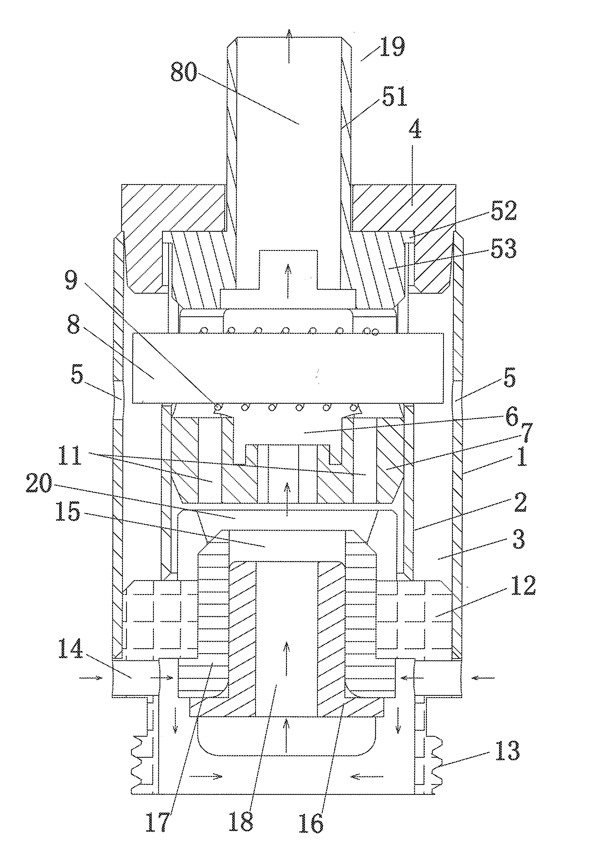
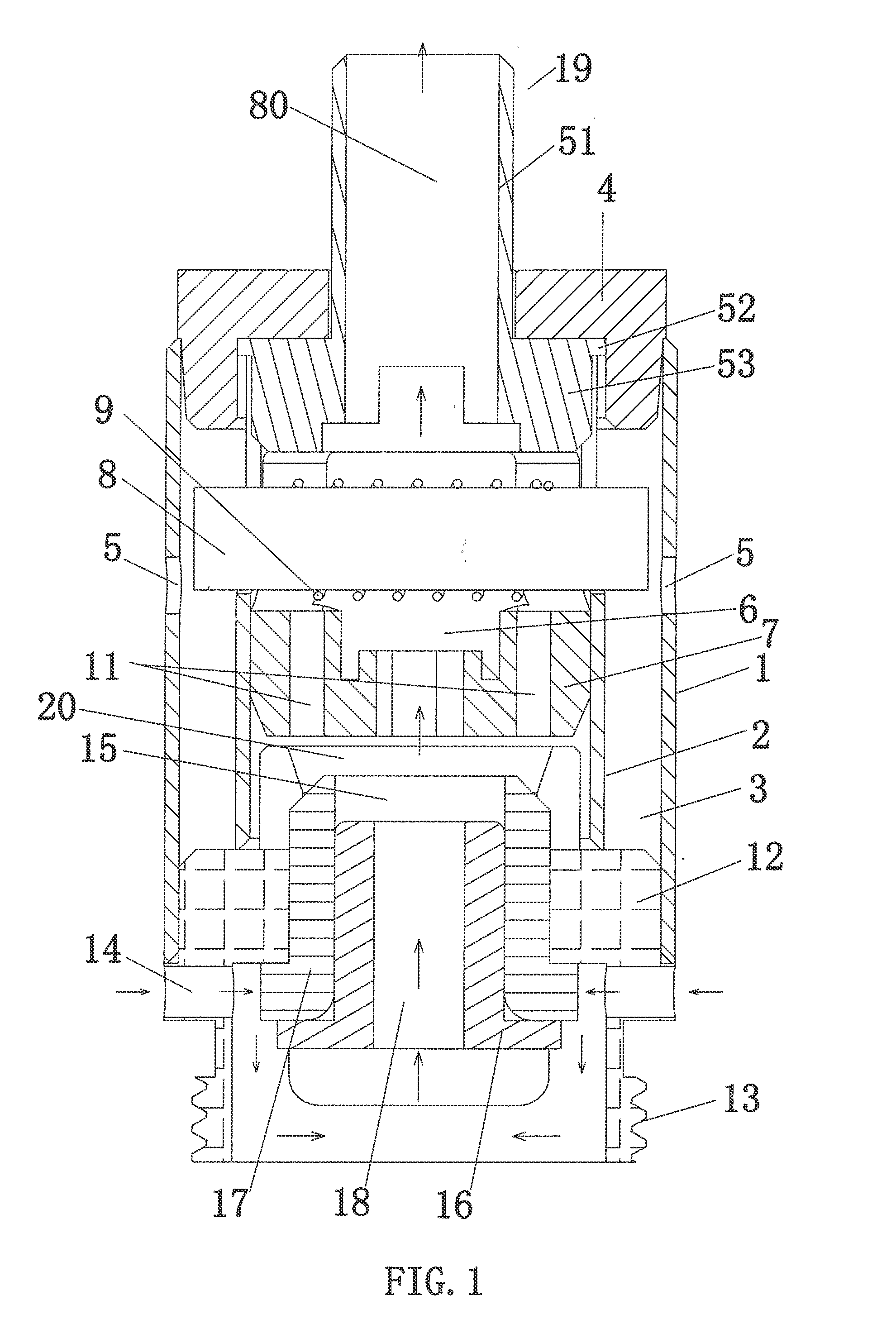
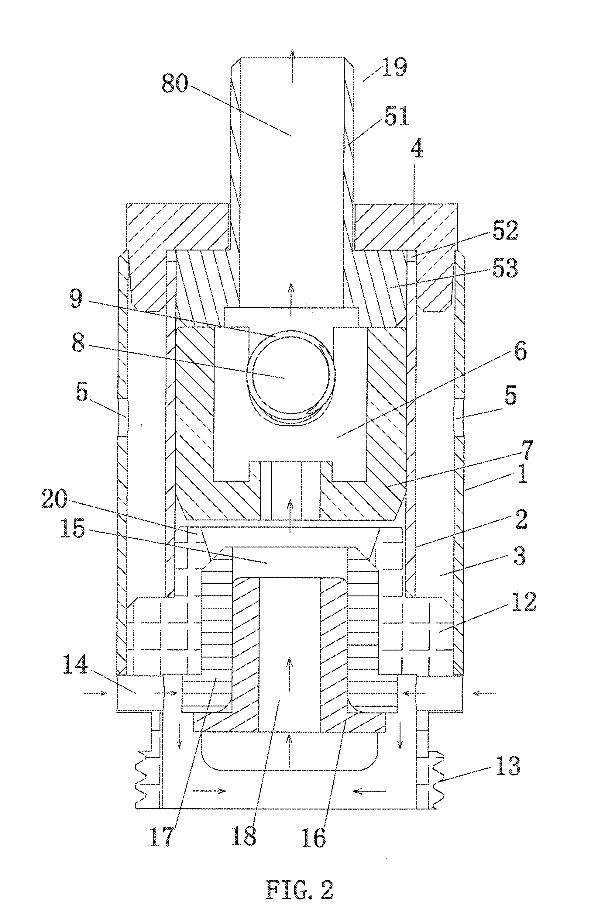
[0037]Referring to FIGS. 1-3, the atomizer head assembly includes an outer tube 1, a smoke pipe 19, a seal member 4, an inner tube 2, a support unit 7, one or more atomizing members 81, a connecting seat 71, and a conductive member 16.

[0038]The atomizer head assembly is disposed inside an atomizer head shell (not shown) which also contains the liquid storage cartridge storing cigarette liquid to be atomized by the atomizer head assembly.

[0039]The outer tube 1 is formed with a hollow tube body and is mounted on the connecting seat 71 of the atomizer had assembly. The outer tube 1 may be mounted on a periphery of the connecting seat 71 by press fitting, or may be mounted on the connecting seat 71 by coupling means such as threads, fixing pins, or screws. The inner tube 2 is centrally arranged within the outer tube 1 such that a liquid storage chamber 3 is formed by a wall of inner tube 2 and a wall of outer tube 1 to store liquid, such as cigarette liquid.

[0040]Meanwhile, one or more ...


PUM


Abstract

The present invention discloses an atomizer head assembly, comprising: an outer tube; an inner tube disposed in the outer tube, having a outer supporter openings formed on a lateral side of wall of the inner tube; a liquid storage chamber formed between the inner tube and the outer tube; a liquid inlet opening formed on a lateral side of wall of the outer tube; and an atomizing member having an end arranged in the one or more outer supporter openings. Moreover, the atomizing head assembly of the present invention comprises a plurality of atomizing members for atomizing liquid electrically connected in parallel and spatially arrange in various configurations, such that the atomizer head assembly can operated with an elevated voltage such that the heat generated per unit time by the atomizer head assembly is increased and the volume of atomized cigarette liquid in the atomizing chamber is increased accordingly.

Description

CROSS-REFERENCE TO RELATED APPLICATIONS[0001]This application claims the benefit under 35 U.S.C. §119 of Chinese Application Number 201320538951.5, filed Aug31, 2013, which is hereby incorporated by reference in its entirety,TECHNICAL FIELD[0002]The present invention generally relates to an electronic cigarette and components thereof, in particular to an atomizing head assembly.BACKGROUND TECHNOLOGY[0003]The electronic cigarette, now mainly used in some developed countries in Europe and the United States, is primarily used to replace traditional cigarettes. With the continuous improvement of living standards in China, people are also constantly pursuing a higher quality of life, and gradually realize the serious harm of smoking; therefore, quitting smoking gradually becomes a common understanding. Therefore, alternatives such as the electronic cigarette are gradually welcomed by people.[0004]Electronic cigarettes have the same look of cigarettes, and have a similar taste or even bet...

Claims


Application Information

Patent Timeline
Patent Type & Authority Applications(United States)
IPC IPC(8): A24F47/00H05B3/14A24F40/10A24F40/46A24F40/485
CPCH05B3/14A24F47/008A24F40/46A24F40/10A24F40/485
Inventor QIU, WEIHUA
Owner JOYETECH CHANGZHOU ELECTRONICS
Why Eureka
Try Eureka