Tank having an inclined partition provided at its ends with through-holes for continuous supply of a supply liquid to a turbine engine

a technology of supply liquid and turbine engine, which is applied in the direction of machines/engines, lubrication elements, and lubrication for crankcase compression engines, etc., can solve the problem that the supply pump no longer suctions the supply liquid

Active Publication Date: 2015-03-05
SN DETUDE & DE CONSTR DE MOTEURS DAVIATION S N E C M A
View PDF15 Cites 3 Cited by
  • Summary
  • Abstract
  • Description
  • Claims
  • Application Information

AI Technical Summary

Problems solved by technology

Consequently, the supply pump no longer suctions the supply liquid, generally lubricating oil in this case, but gas.
However, cert...

Method used


Image

  • Tank having an inclined partition provided at its ends with through-holes for continuous supply of a supply liquid to a turbine engine
  • Tank having an inclined partition provided at its ends with through-holes for continuous supply of a supply liquid to a turbine engine
  • Tank having an inclined partition provided at its ends with through-holes for continuous supply of a supply liquid to a turbine engine

Examples


Embodiment Construction

[0006]The invention is intended to at least partially solve the problems encountered in the prior art solutions. The invention is intended in particular to enable the supply liquid to be supplied at least to certain elements of the turbine engine under numerous circumstances, while limiting the mass and bulk of the turbine engine.

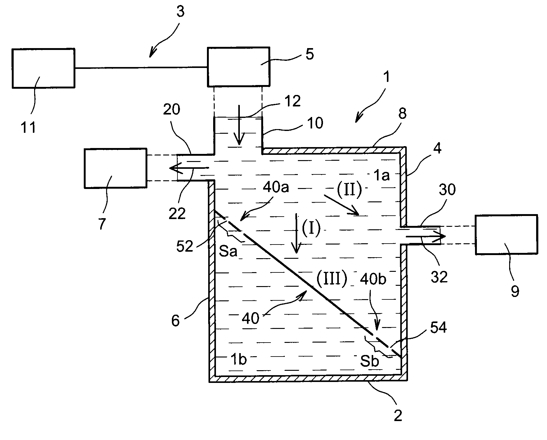
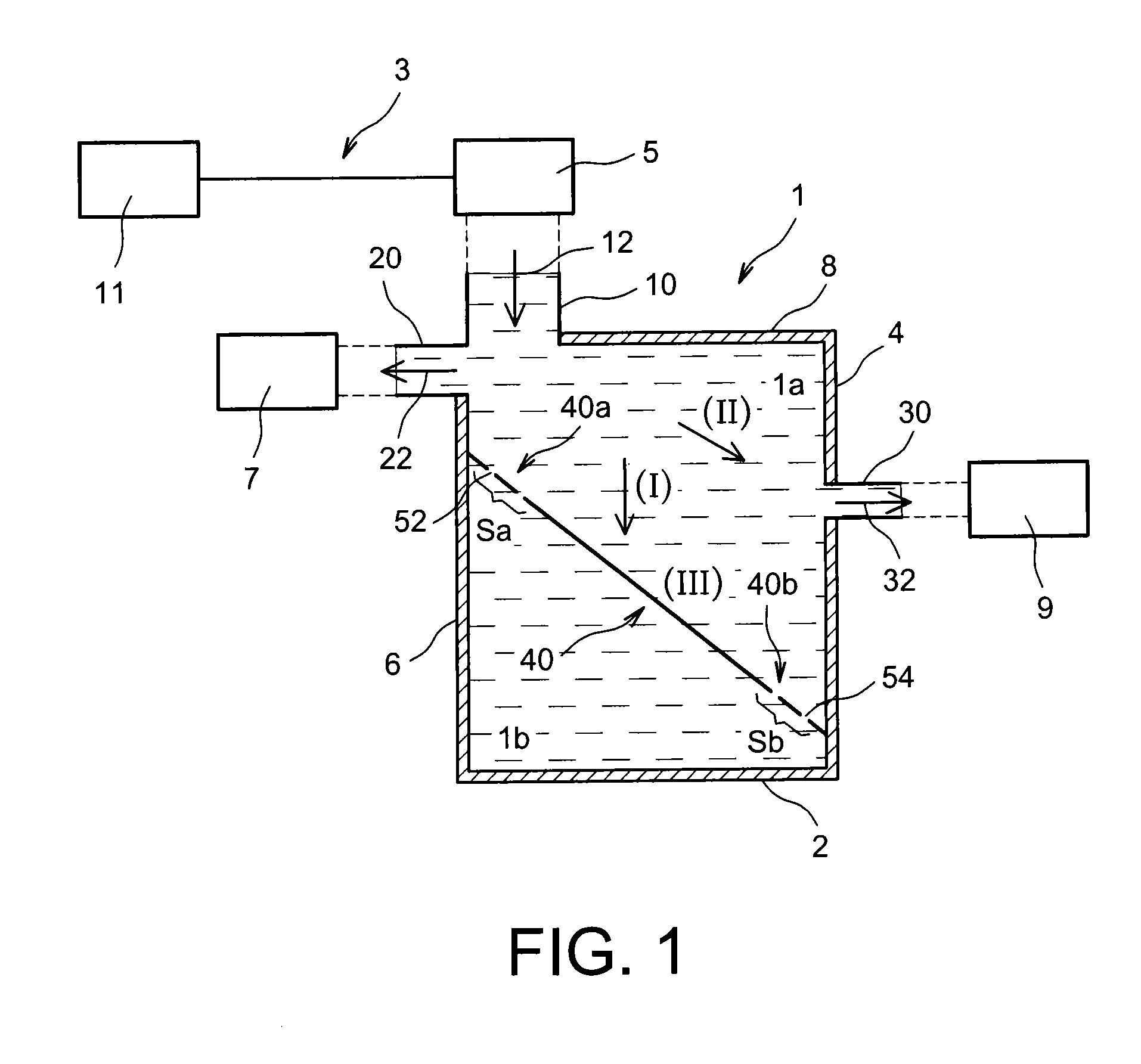
[0007]In this regard, the invention relates to a supply liquid tank for a turbine engine, comprising a first compartment and a second compartment wherein the bottom of the tank is located,

[0008]the first compartment having an inlet for supply liquid, in particular lubricant, a first outlet and a second outlet located according to a first direction, in particular similar to a height of the tank, with respect to the first outlet so that the second outlet is closer to the bottom of the tank than the first outlet,

[0009]the tank comprising a partition separating the first compartment and the second compartment,

[0010]the partition having a first end and a second ...


PUM


Abstract

The tank for a turbine engine comprises a partition separating a first compartment from a second compartment of the tank , the partition having a first end and a second end, the second end being closer to the bottom of the tank than the first end, the partition being inclined from the first end to the second end in the first direction and in the direction of the first outlet to the second outlet , the partition comprising at least one first Through-hole near the first end and at least one second through-hole closer to the second end than the first hole.

Description

TECHNICAL FIELD [0001]This invention belongs to the technical field of turbine engine tanks. More specifically, the invention relates to the supply of a supply liquid to a turbine engine, in particular the provision of a lubricant to a turboprop engine.PRIOR ART [0002]The turbine engine lubricating system comprises, in a known manner, an auxiliary tank connected to a main tank. The auxiliary tank comprises an inlet fluidically connected to a pump for supplying the supply liquid, for example lubricant. The tank also comprises two outlets, one supplying one or more bearings, and the other supplying a propeller pitch changing mechanism.[0003]In the event of zero gravity or inclination of the turbine engine, in particular in the event the main tank of the lubricating system is turned over, a significant amount of lubricant in the main system moves to the upper end of said tank.[0004]Consequently, the supply pump no longer suctions the supply liquid, generally lubricating oil in this cas...

Claims


Application Information

Patent Timeline
IPC IPC(8): F01D25/20F01D25/18
CPCF01D25/18F01D25/20F01M2011/0095F16N17/06B64D37/08F01M11/067F16N19/00
Inventor LAIGLE, ANTOINELE GOUELLEC, GILLESWAISSI, BELLAL
Owner SN DETUDE & DE CONSTR DE MOTEURS DAVIATION S N E C M A
Why Eureka
Try Eureka