Shear bonding device and shear bonding method of metal plates

a shear bonding and metal plate technology, applied in the direction of welding devices, soldering devices, manufacturing tools, etc., can solve the problems that the shear bonding method mainly used in the conventional butt joint of metal plates is difficult to apply to bonding nonferrous metal plates or thick metal plates, and achieve the effect of strengthening the bonding strength of the bonding portions

Active Publication Date: 2015-03-05
SUNG WOO HITECH +1
View PDF4 Cites 6 Cited by
  • Summary
  • Abstract
  • Description
  • Claims
  • Application Information

AI Technical Summary

Benefits of technology

[0012]Another embodiment of the present invention provides a shear bonding device and a shear bonding method of metal plates having further advantages of agitating materials in the bonding portions through plastic flow and further strengthening bonding strength of the bonding portions by heatin

Problems solved by technology

In addition, a melting method such as welding mainly used in a conventional butt joint of the

Method used


Image

  • Shear bonding device and shear bonding method of metal plates
  • Shear bonding device and shear bonding method of metal plates
  • Shear bonding device and shear bonding method of metal plates

Examples


Embodiment Construction

[0044]An exemplary embodiment of the present invention will hereinafter be described in detail with reference to the accompanying drawings.

[0045]Since size and thickness of each component illustrated in the drawings are arbitrarily represented for ease of explanation, the present invention is not limited to the drawings. Thicknesses of many parts and regions are enlarged.

[0046]In addition, description of components that are not necessary for explaining the present exemplary embodiments will be omitted.

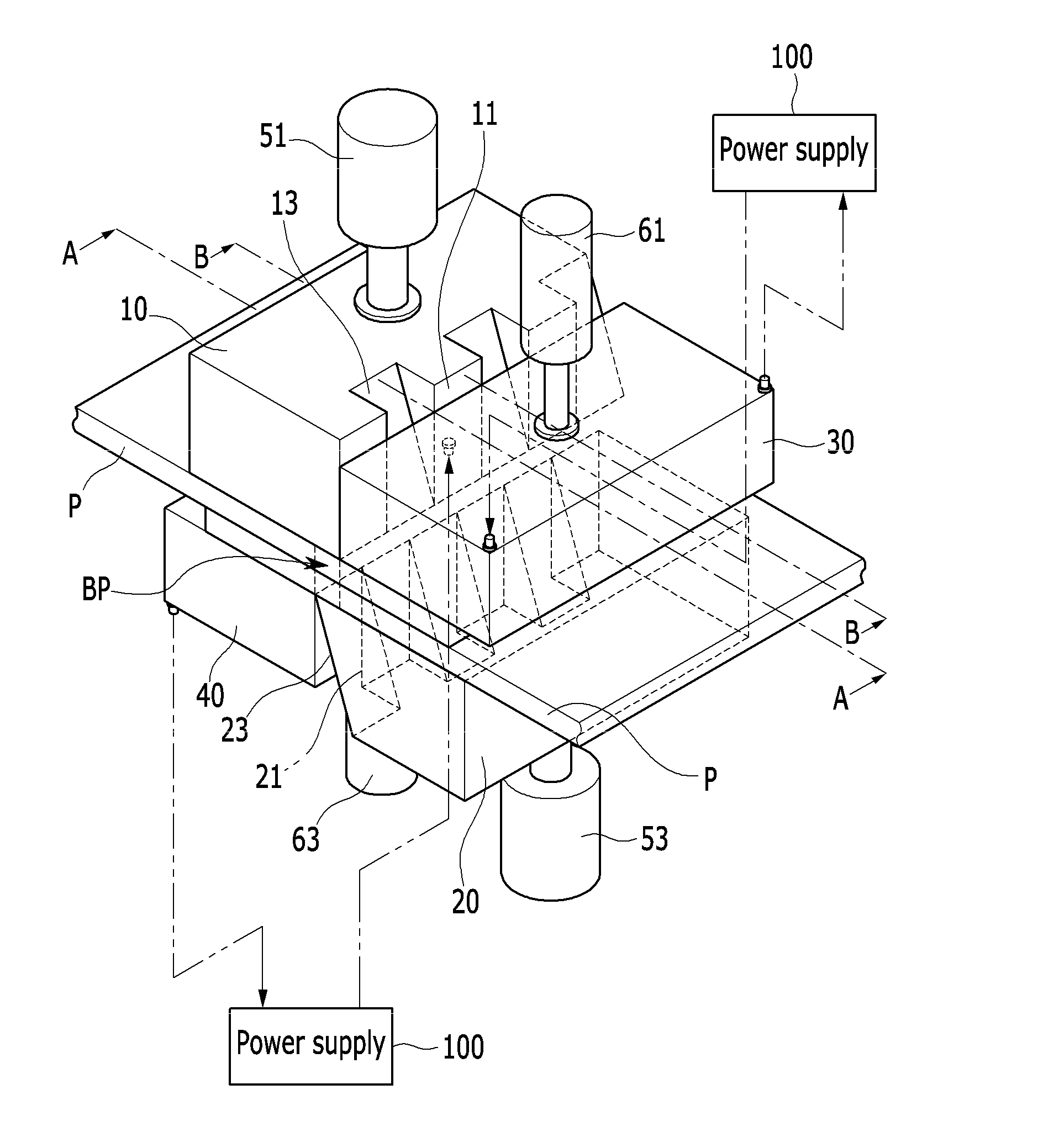
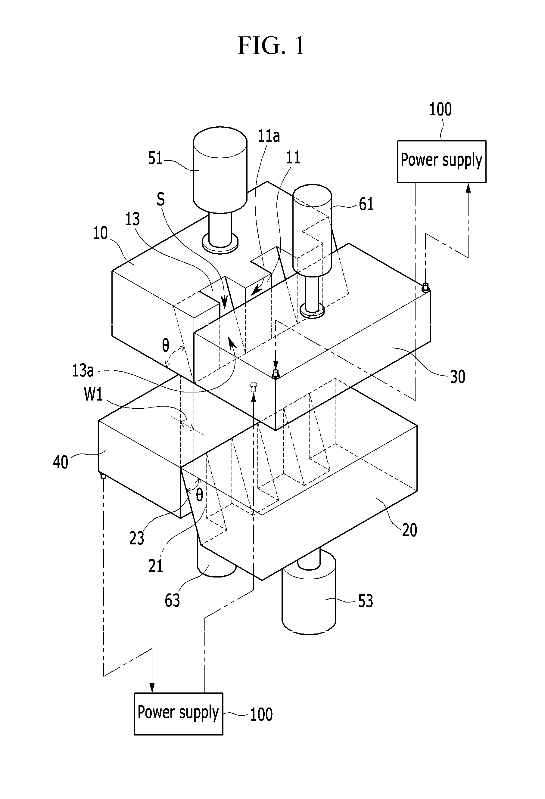
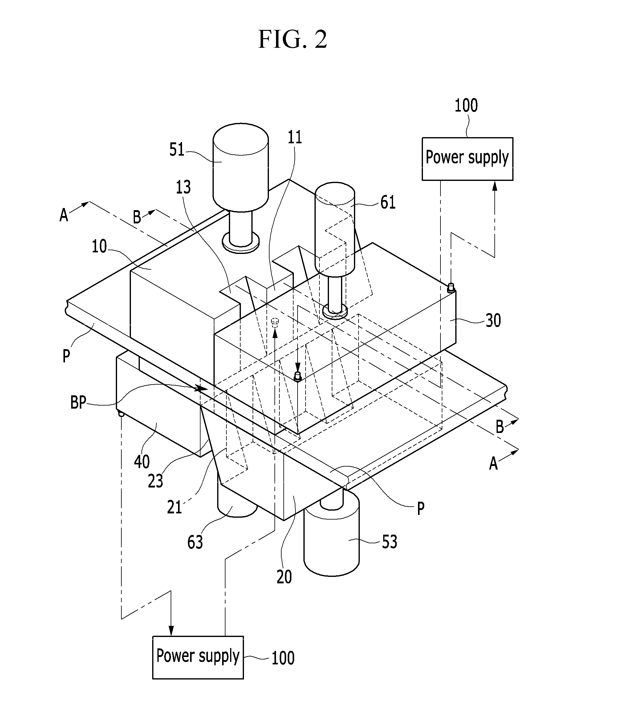
[0047]FIG. 1 is a perspective view of a shear bonding device according to an exemplary embodiment of the present invention, FIG. 2 is a perspective view of a shear bonding device according to an exemplary embodiment of the present invention with metal plates being supplied into the shear bonding device, and FIG. 3 is a perspective view of an upper or a lower shear bonding mold applicable to a shear bonding device according to an exemplary embodiment of the present invention.

[0048]A she...


PUM

PropertyMeasurementUnit
Forceaaaaaaaaaa
Pressureaaaaaaaaaa
Angleaaaaaaaaaa

Abstract

A shear bonding device and a shear bonding method of metal plates are disclosed. The shear bonding device may include: an upper shear bonding mold having more than one upper perpendicular tooth and more than one upper slanted tooth formed alternately on a front end surface thereof; a lower shear bonding mold overlapped with the upper shear bonding mold in a vertical direction by a predetermined width below the upper shear bonding mold, and having more than one lower perpendicular tooth corresponding to the more than one upper slanted tooth and the more than one upper perpendicular tooth corresponding to the more than one lower slanted tooth formed alternately on a front end surface confronting the upper shear bonding mold; an upper heating clamper including a front end surface contacting with the upper perpendicular tooth of the upper shear bonding mold and adapted to generate heat by receiving power from a power supply; a lower heating clamper including a front end surface contacting with the lower perpendicular tooth of the lower shear bonding mold and adapted to generate heat by receiving power from the power supply; upper and lower pressing cylinders moving the upper and lower shear bonding molds upwardly or downwardly so as to apply load; and upper and lower clamping cylinders moving the upper and lower heating clampers upwardly or downwardly so as to apply clamping force and load, wherein the metal plates are disposed between the upper shear bonding mold and heating clamper, and the lower shear bonding mold and heating clamper.

Description

CROSS-REFERENCE TO RELATED APPLICATION[0001]This application claims priority to and the benefit of Korean Patent Application No. 10-2013-0105737 filed in the Korean Intellectual Property Office on Sep. 3, 2013, the entire contents of which are incorporated herein by reference.BACKGROUND OF THE INVENTION[0002](a) Field of the Invention[0003]The present invention relates to a shear bonding device and a shear bonding method of metal plates. More particularly, the present invention relates to a shear bonding device and a shear bonding method of metal plates that can shear and bond portions of an overlapped two metal plates by applying pressure along bonding portions.[0004](b) Description of the Related Art[0005]A butt joint of metal plates, generally, is one of jointing technique of metal plates which is widely applied to entire industries. The butt joint is particularly used to bond stamping materials such as a tailor welded blanks (TWBs) that are manufactured by bonding metal plates h...

Claims


Application Information

Patent Timeline
IPC IPC(8): B23K20/02B23K31/02B23D35/00
CPCB23K20/023B23K2201/18B23K31/02B23D35/001B23D31/00B23K20/028B23K2101/185B23K20/025
Inventor JIN, IN TAI
Owner SUNG WOO HITECH
Why Eureka
Try Eureka