Magnetic field generator for magnetocaloric thermal appliance
a magnetocaloric thermal appliance and generator technology, applied in the direction of permanent magnets, magnetic bodies, electrical appliances, etc., can solve the problems of increasing the weight accordingly, limiting the useful calorific output, and difficult to handle, etc., to achieve simple geometrical shapes, easy to manufacture, and easy to assemble
- Summary
- Abstract
- Description
- Claims
- Application Information
AI Technical Summary
Benefits of technology
Problems solved by technology
Method used
Image

Examples
first embodiment
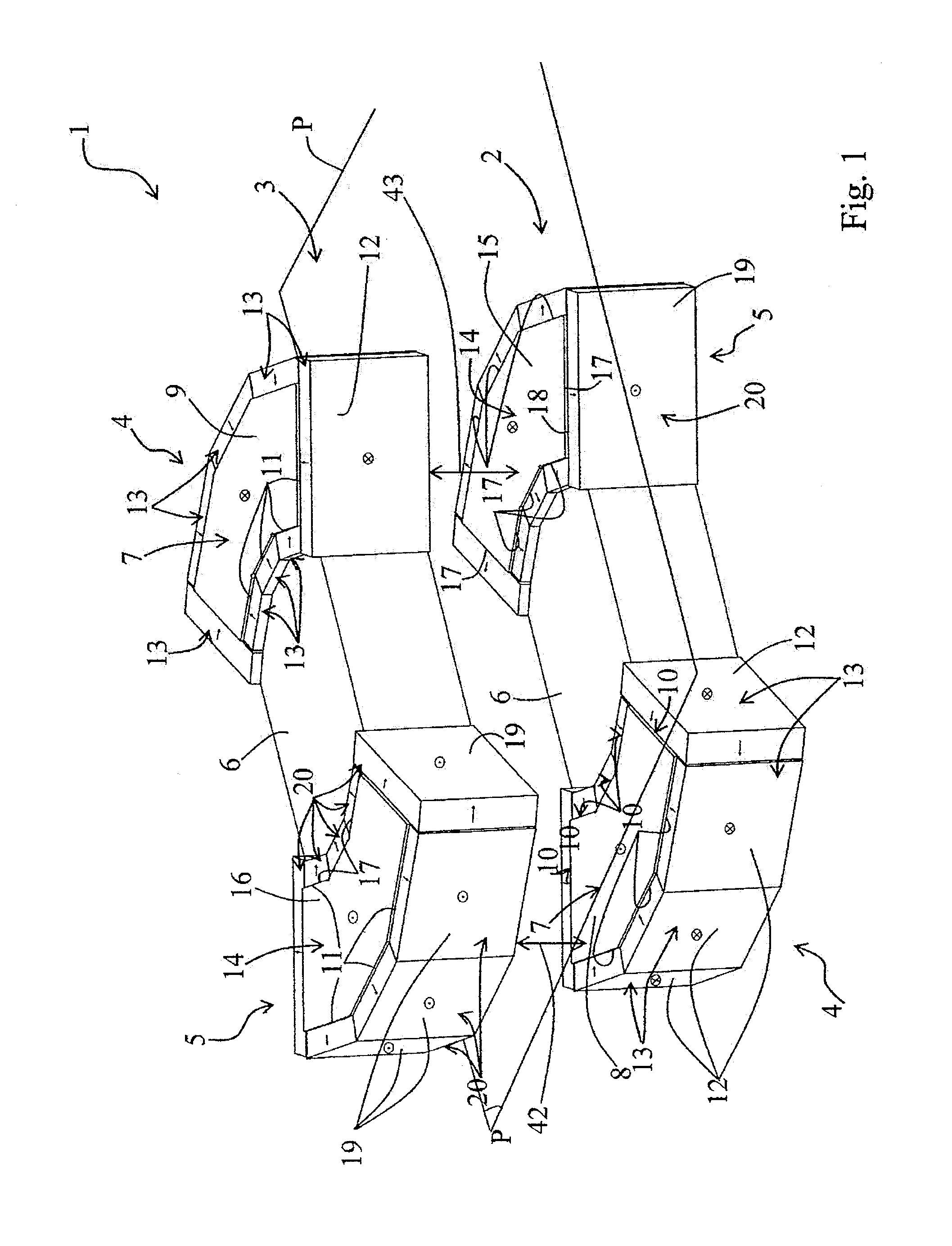
[0032]FIG. 1 is a magnetic field generator 1 according to the invention. This magnetic field generator 1 comprises a first magnetizing structure 2 and a second magnetizing structure 3 that are identical, parallel, mounted head-to-tail and arranged opposite to each other to delimit between them two diametrically opposite air gaps 42, 43. Each magnetizing structure 2, 3 comprises a first magnetizing assembly 4 and a second magnetizing assembly 5. The two magnetizing structures 2 and 3 are arranged parallel with respect to each other, on either side of a plane P and so that the first magnetizing assembly 4 of the first magnetizing structure 2 is opposite to the second magnetizing assembly 5 of the second magnetizing structure 3 and that the second magnetizing assembly 5 of the first magnetizing structure 2 is opposite to the first magnetizing assembly 4 of the second magnetizing structure 3. The magnetizing assemblies 4, 5 of each magnetizing structure 2, 3 are connected together by a ...
second embodiment
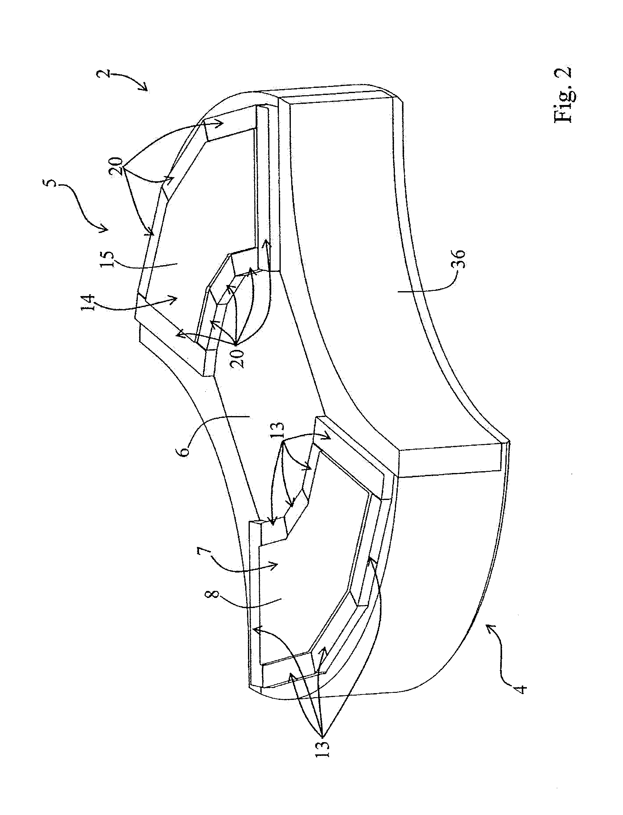
[0042]FIG. 5 represents a second embodiment variant of the magnetic field generator 27. This magnetic field generator 27 corresponds to that of FIG. 1 mounted in a frame 36 as represented in FIG. 2 and wherein a third magnetizing structure 37 has been mounted. This third magnetizing structure 37 comprises two polygonal and uniformly magnetized central magnets 38 and 39. A first central magnet 38 is mounted between the first magnetizing assembly 4 of the first magnetizing structure 2 and the second magnetizing assembly 5 of the second magnetizing structure 3, while the other central magnet 39 is mounted between the second magnetizing assembly 5 of the first magnetizing structure 2 and the first magnetizing assembly 4 of the second magnetizing structure 3 The central magnets 38, 39 comprise two active sides 40 and 41 parallel to each other and to the active sides 8, 15 of the central magnets 7, 14 of the first and second magnetizing structures 2, 3. As an example, the central magnets ...
third embodiment
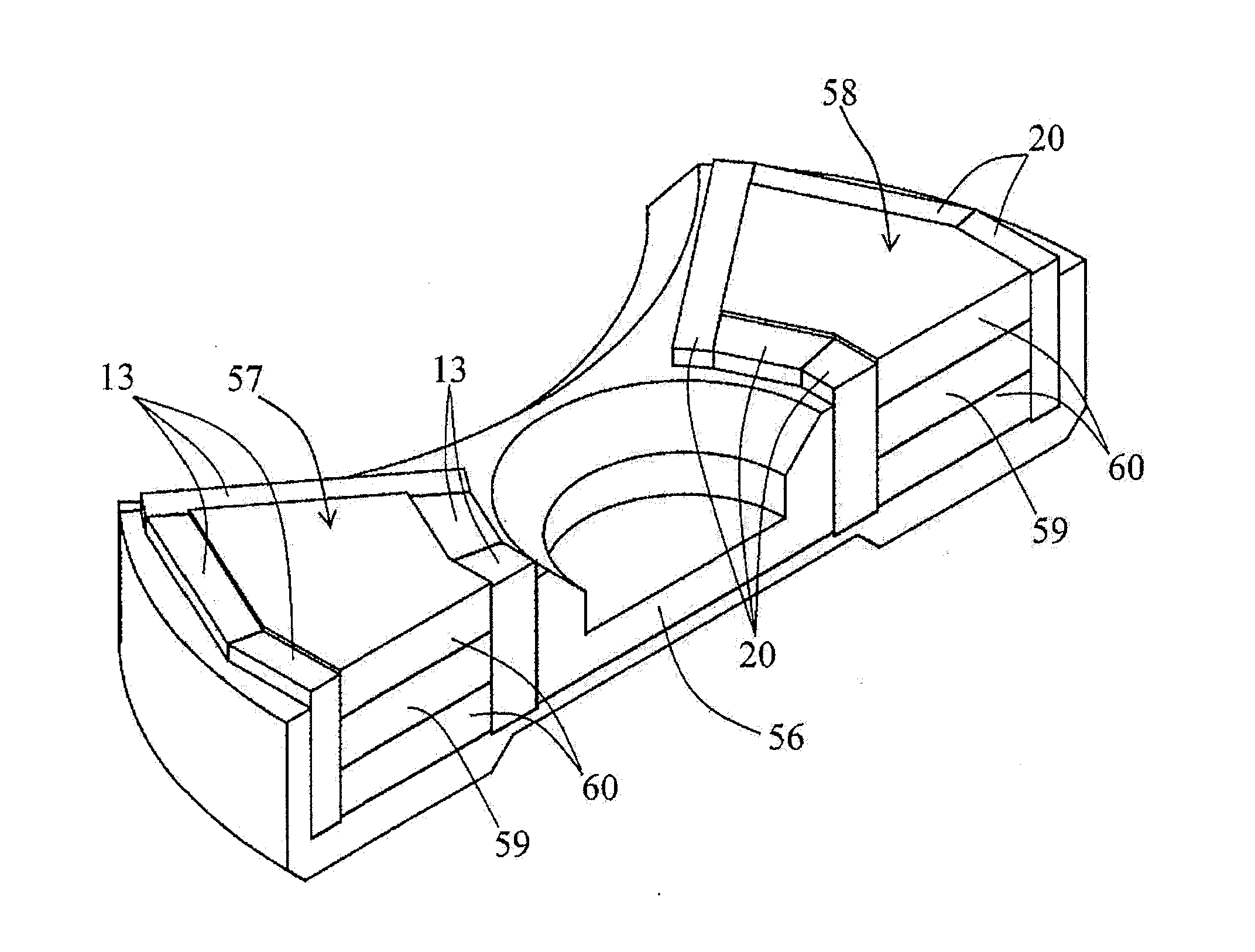
[0044]FIG. 6 represents a third embodiment variant of a magnetic field generator 55 that differs from the magnetic field generator 1 of FIG. 1 by the configuration of the first 24 and second 25 magnetizing assemblies. Each central magnet 7, 14 is topped on its active side 8, 15 with a pole piece or magnetic concentration piece 26 made out of a ferromagnetic material. Such a pole piece 26 allows concentrating the magnetic flux coming from the magnetic belt 13, 20 and from the central magnet 7, 14 in the air gaps 42, 43. As for the central magnet 7, 14, the lateral sides 53 of the pole piece 26 are in contact with the internal sides 11, 18 of the magnetic belt 13, 20. To facilitate understanding, two permanent magnets of the magnetic belts 13, 20 have been removed from the first magnetizing assembly 24 of the first magnetizing structure 22 and from the second magnetizing assembly 25 of the second magnetizing structure 23.
[0045]In the magnetic field generator 55 represented in FIG. 6, ...
PUM
| Property | Measurement | Unit |
|---|---|---|
| magnetic field | aaaaa | aaaaa |
| magnetic remanence | aaaaa | aaaaa |
| magnetic remanence | aaaaa | aaaaa |
Abstract
Description
Claims
Application Information
 - R&D
- Intellectual Property
- Life Sciences
- Materials
- Tech Scout
- Unparalleled Data Quality
- Higher Quality Content
- 60% Fewer Hallucinations
Browse by: Latest US Patents, China's latest patents, Technical Efficacy Thesaurus, Application Domain, Technology Topic, Popular Technical Reports.
© 2025 PatSnap. All rights reserved.Legal|Privacy policy|Modern Slavery Act Transparency Statement|Sitemap|About US| Contact US: help@patsnap.com