
Display device

Inactive Publication Date: 2015-03-05
BOE TECH GRP CO LTD +1
View PDF13 Cites 4 Cited by
  • Summary
  • Abstract
  • Description
  • Claims
  • Application Information

AI Technical Summary

Benefits of technology

The present invention aims to reduce color coordinate deviations in display devices. The invention incorporates a green backlight and a transparent filter in conjunction with the green filter on the existing filter substrate to achieve display. The driving circuit controls the two combinations of light sources and filters, ensuring that the color coordinates meet requirements of Adobe red and blue color coordinates when the white backlight is used and the red and blue filters are driven, and also ensuring that the color coordinates meet requirements of Adobe green color coordinates when the green backlight is used and the transparent filter is driven. This results in reduced deviation of the color coordinates of the white light from the standard while meeting the Adobe percent specification. The invention also allows for adjustment of mixed light color and enhancement of brightness, as well as cost reduction due to the saved manufacturing process for the filter substrate.

Problems solved by technology

However, the Adobe matching rate is still far from 100%.
However, with the same power consumption, the blue and green LEDs plus red phosphor have a lower overall light efficiency, and its luminous flux is reduced by more than half compared with that of the blue LED plus red-green phosphors.
However, since the deviations are large, it is difficult to correct the color coordinates of the white light to meet the standard by adjusting the color block of the white LED.
Therefore, most display devices in the prior art have defects of large brightness loss, large deviations of color coordinates of the white light from the standard or low color rendering capability.

Method used


Image

  • Display device
  • Display device
  • Display device

Examples


Embodiment Construction

[0024]Hereinafter, embodiments of the present invention will be described in detail in conjunction with the drawings.

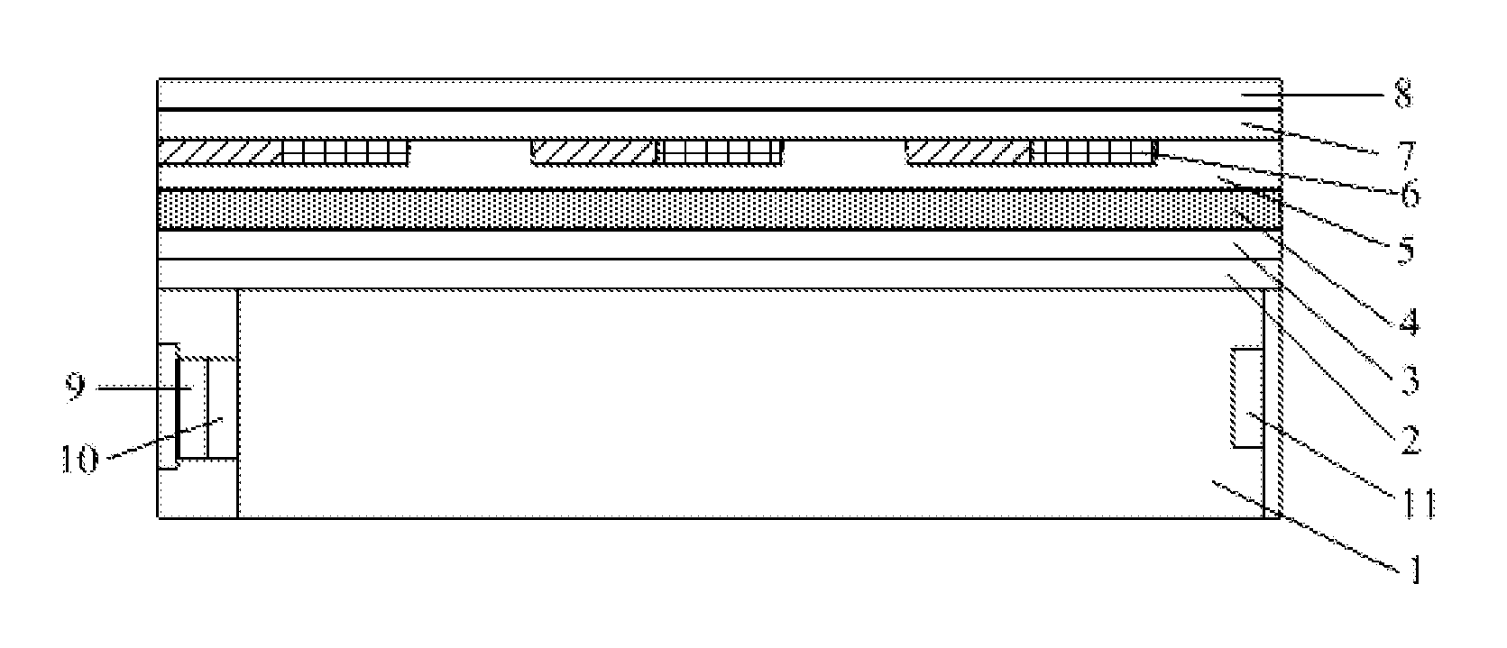
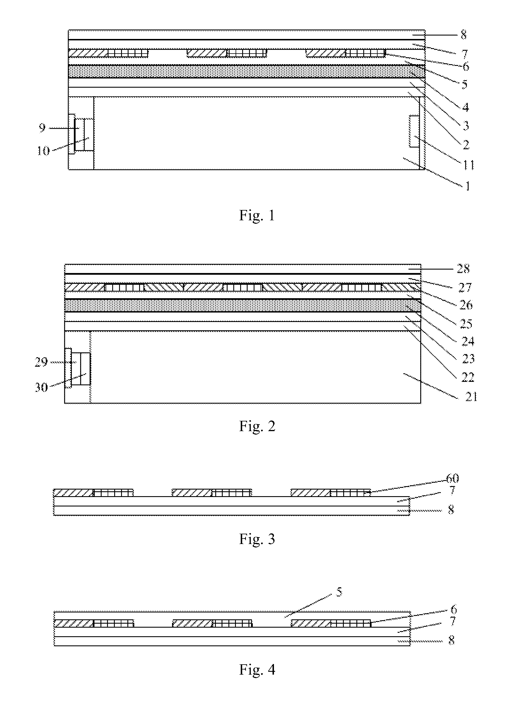
[0025]FIG. 1 is a schematic view illustrating a structure of a display device according to an embodiment of the present invention.

[0026]As shown in FIG. 1, similar to those in a display device in the prior art, a lower polarizing layer 2 is formed on a backlight module 1, a lower substrate 3 is formed on the lower polarizing layer 2, a liquid crystal layer 4 is disposed between the lower substrate 3 and a protective layer 5, a filter layer 6 is formed on the protective layer 5, an upper substrate 7 is formed on the filter layer 6 and an upper polarizing layer 8 is formed on the upper substrate 7.

[0027]The display device according to the embodiment of the present invention is different from that in the prior art in that the filter layer 6 includes a plurality of sets of filters and each set of filters consist of red, blue and transparent filters, wherein the green filt...


PUM


Abstract

The present invention relates to a display device, including a display panel, a backlight module under the display panel and a driving circuit, wherein, a filter substrate of the display panel includes a plurality sets of filters each of which includes a red filter, a blue filter and a transparent filter; the backlight module includes a white backlight and a green backlight; and the driving circuit drives the white backlight to emit light and drives a red and blue pixels corresponding to the red and blue filters respectively to display at odd frames (or even frames), and drives the green backlight to emit light and drives a transparent pixel corresponding to the transparent filter to display at even frames (or odd frames). With the above technical solution, the Adobe RGB color coordinates can be met while a color of a mixed light can be adjusted and brightness can be enhanced.

Description

FIELD OF THE INVENTION[0001]The present invention relates to the field of display technology, and particularly to a display device.BACKGROUND OF THE INVENTION[0002]A conventional display device mainly includes a display panel, a backlight module and a control system. FIG. 2 is a schematic view illustrating a structure of a display device in the prior art. As shown in FIG. 2, the display device includes a backlight module 21, a lower polarizing layer 22 is formed on the backlight module 21, a lower substrate 23 is formed on the lower polarizing layer 22, a liquid crystal layer 24 is disposed between the lower substrate 23 and a protective layer 25, and a filter layer 26 is formed on the protective layer 25, wherein, the filter layer 26 is formed of red, green and blue filters which are arranged alternately, an upper substrate 27 is formed on the filter layer 26, and an upper polarizing layer 28 is formed on the upper substrate 27. The backlight module 21 includes a backlight consisti...

Claims


Application Information

Patent Timeline
IPC IPC(8): G09G3/34G09G3/36
CPCG09G3/3413G09G3/3607G09G2320/0626G09G2320/0233G09G2320/0242G09G2310/0235
Inventor LIN, LIFENGZHAN, HONGMINGWANG, YONGCAN
Owner BOE TECH GRP CO LTD
Learn More