Airflow modifying element for suppressing airflow noise

a technology of airflow and modifying elements, applied in the direction of propulsive elements, marine propulsion, vessel construction, etc., can solve the problems of noise or whistling in the surrounding area, and achieve the effect of reducing airflow nois

Inactive Publication Date: 2015-03-05
GENERAL ELECTRIC CO
View PDF4 Cites 14 Cited by
  • Summary
  • Abstract
  • Description
  • Claims
  • Application Information

AI Technical Summary

Benefits of technology

[0007]In accordance with aspects of the invention, a rotor blade assembly is provided having at least one rotor blade including a body shell extending between a blade root and a blade tip. The body shell has a pressure side surface and a suction side surface. The rotor blade includes at least one drain hole having a diameter. The drain hole is configured on the body shell of the rotor blade. At least one airflow modifying element is configured on the body shell a predetermined distance from the drain hole such that the airflow modifying element reduces airflow noise caused by the drain hole. In addition, the predetermined distance is substantially equal to the diameter of the drain hole.
[0008]In a further aspect, another embodiment of a rotor blade assembly for a wind turbine is disclosed. The rotor blade assembly includes a rotor blade having a suction side surface and a pressure side surface. Further, the rotor blade assembly includes a drain hole configured on the pressure side surface. At least one airflow modifying element is configured on the pressure side surface. The airflow modifying element is located a predetermined distance from the drain hole such that the airflow modifying element reduces airflow noise caused by the drain hole. In addition, the airflow modifying element extends a perpendicular distance from the surface of the blade to define a maximum height, the maximum height being a function of a boundary layer thickness.
[0009]In still another aspect, a method for reducing airflow noise caused by a drain hole of a wind turbine is disclosed. The method includes measuring an airflow noise near a wind turbine using a sensor; providing the airflow noise to a controller; and, actuating an airflow modifying element, by the controller, when the airflow noise exceeds a predetermined threshold. The airflow modifying element is located a predetermined distance from the drain hole. Further, the predetermined distance is equal to or less than the diameter of the drain hole. Moreover, the airflow modifying element reduces the airflow noise caused by the drain hole when the airflow modifying element is in an actuated position.

Problems solved by technology

Such drain holes, however, may cause noise or whistling in surrounding areas due to the interaction of a moving mass (e.g. air inside the drain hole) with a shear layer at the opening of the drain hole.
More specifically, the moving mass may cause shear layer instabilities that, in return, amplify the movement of the mass.

Method used


Image

  • Airflow modifying element for suppressing airflow noise
  • Airflow modifying element for suppressing airflow noise
  • Airflow modifying element for suppressing airflow noise

Examples


Embodiment Construction

[0018]Reference now will be made in detail to embodiments of the invention, one or more examples of which are illustrated in the drawings. Each example is provided by way of explanation of the invention, not limitation of the invention. In fact, it will be apparent to those skilled in the art that various modifications and variations can be made in the present invention without departing from the scope or spirit of the invention. For instance, features illustrated or described as part of one embodiment can be used with another embodiment to yield a still further embodiment. Thus, it is intended that the present invention include such modifications and variations as come within the scope of the appended claims and their equivalents.

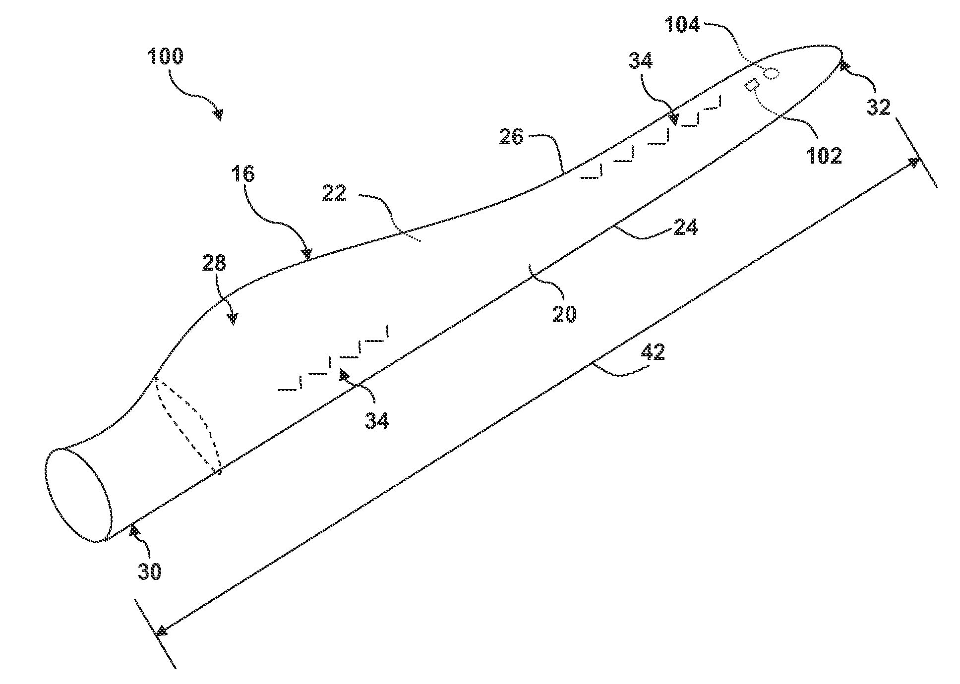
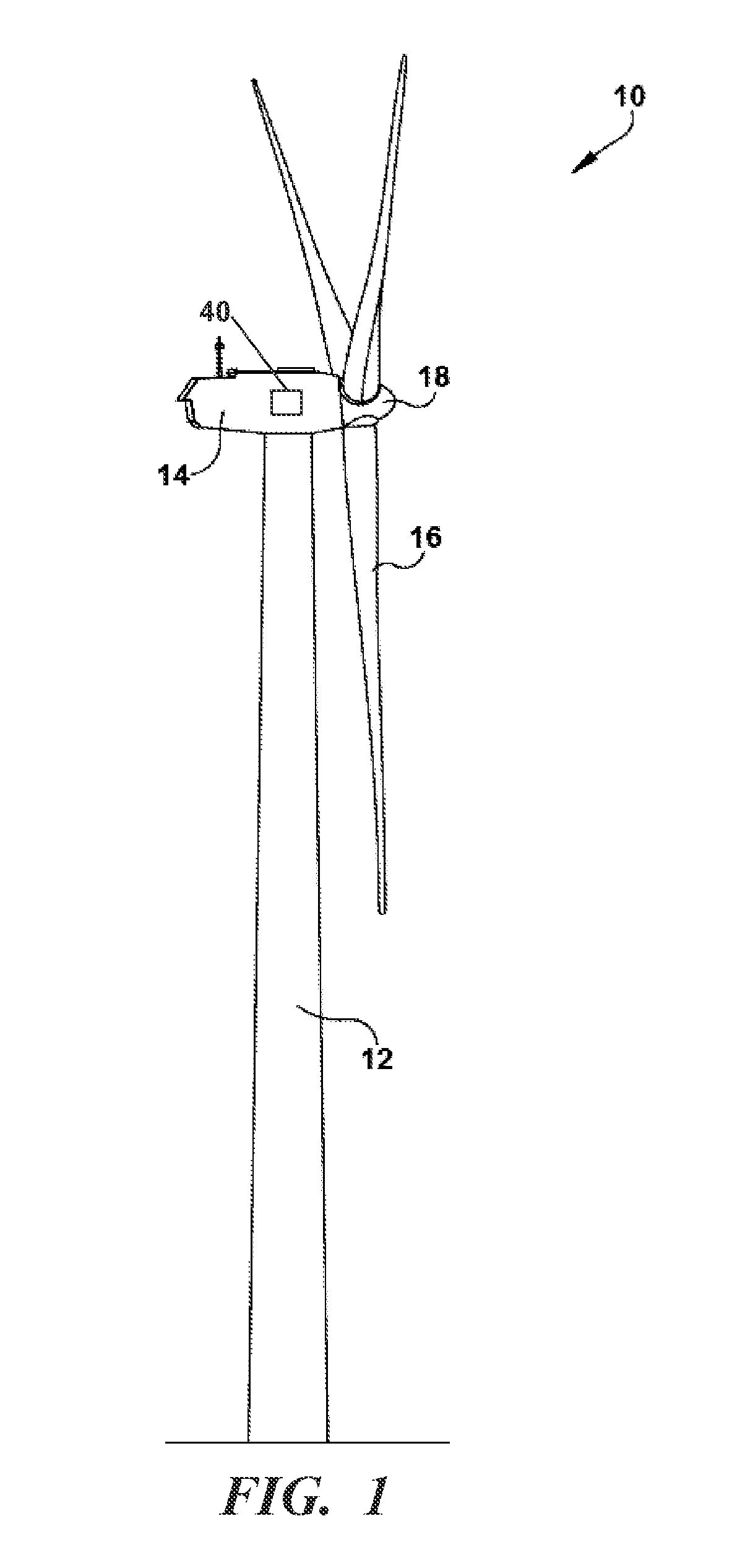
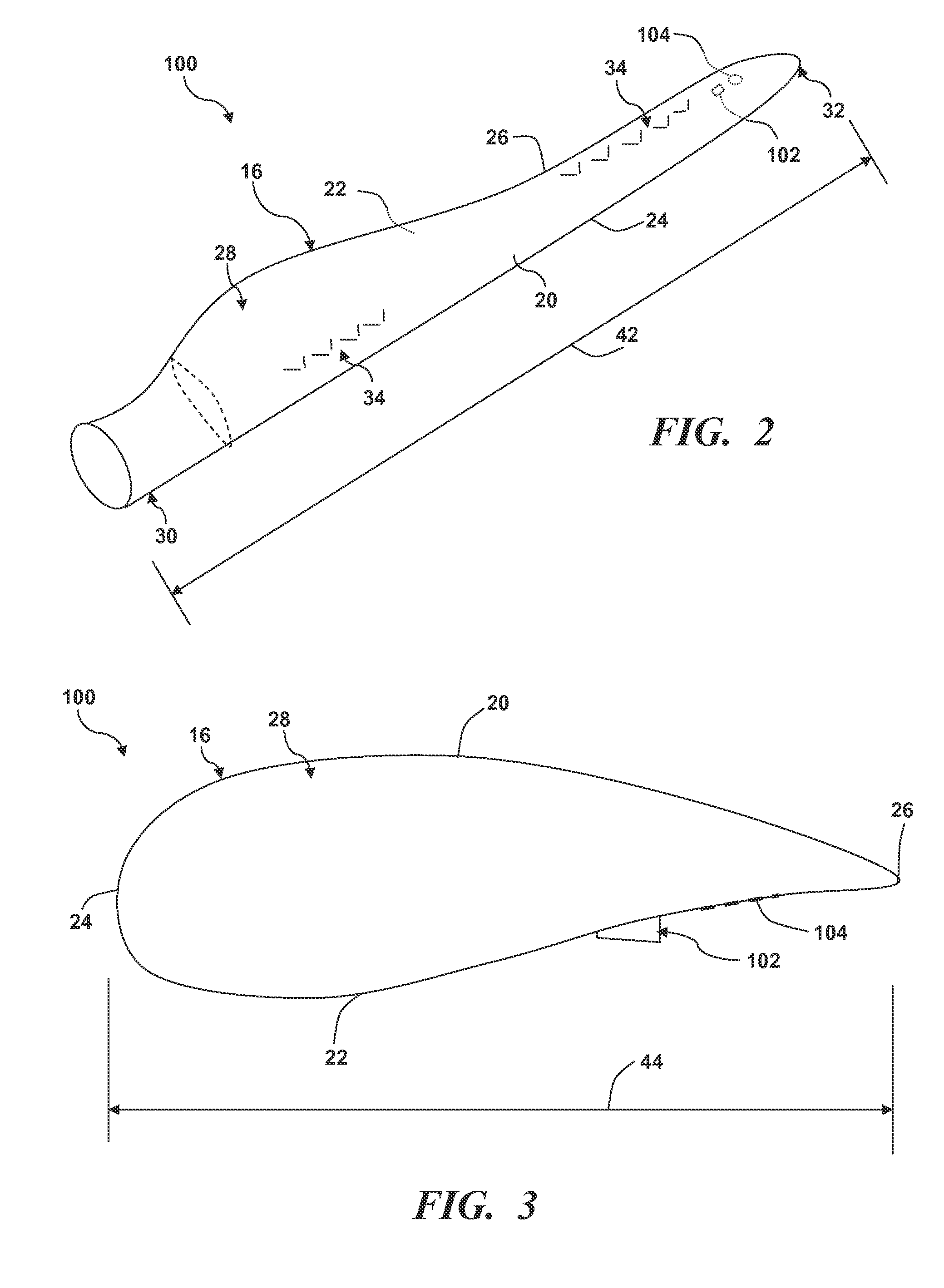
[0019]The present invention is described herein as it may relate to a component of a wind turbine blade. It should be appreciated, however, that the unique airflow modifying element configuration in accordance with principles of the invention is not limite...


PUM


Abstract

A rotor blade assembly is provided having an airflow modifying element for suppressing airflow noise caused by a drain hole. The rotor blade assembly includes at least one rotor blade including a body shell extending between a blade root and a blade tip. Further, the rotor blade includes at least one drain hole having a diameter. The drain hole is configured within the body shell of the rotor blade. At least one airflow modifying element is configured on the body shell a predetermined distance from the drain hole such that the airflow modifying element reduces airflow noise caused by the drain hole. In one embodiment, the predetermined distance is substantially equal to the diameter of the drain hole.

Description

FIELD OF THE INVENTION [0001]The present invention relates generally to the field of wind turbines, and more particularly to a rotor blade assembly for a wind turbine having airflow modifying elements for suppressing airflow noise.BACKGROUND OF THE INVENTION [0002]Wind turbine rotor blades are the primary elements of wind turbines for converting wind energy into electrical energy. The working principle of the blades resembles that of an airplane wing. The blades have the cross-sectional profile of an airfoil such that, during operation, air flows over the blade producing a pressure difference between the sides. Consequently, a lift force, which is directed from a pressure side towards a suction side, acts on the blade. The lift force generates torque on the main rotor shaft, which is geared to a generator for producing electricity.[0003]Some rotor blades may include one or more drain holes used for draining water that may become trapped within the rotor blade during operation. The d...

Claims


Application Information

Patent Timeline
Patent Type & Authority Applications(United States)
IPC IPC(8): F03D1/06F03D7/04F03D7/02
CPCF03D1/0641F03D7/042F03D7/022F03D1/0633F05B2260/96Y02E10/72F05B2240/3062F05B2240/122
Inventor DROBIETZ, ROGER
Owner GENERAL ELECTRIC CO
Why Eureka
Try Eureka