Imaging apparatus and imaging method

a technology of imaging apparatus and imaging object, which is applied in the field of imaging apparatus and imaging method, can solve the problems of difficult to observe the structure and the like of an imaging object, difficult to obtain a high image contrast, and poor image contrast, and achieves simple configuration, good image contrast, and the effect of performing imaging

Active Publication Date: 2015-03-05
DAINIPPON SCREEN MTG CO LTD
View PDF1 Cites 4 Cited by
  • Summary
  • Abstract
  • Description
  • Claims
  • Application Information

AI Technical Summary

Benefits of technology

[0008]This invention was developed in view of the above problems and aims to provide a technology capable of providing a good image contrast and performing imaging by a simple configuration even if an imaging object is a relatively thin biological sample.
[0012]In such a configuration, the strip-like light shield crosses the light emitting part to shield a part of the light emitting part when the light emitting part is viewed from the strip-like region of the carrying surface. Conversely, if the imaging object is viewed from the light emitting part side, a shadow of the light shield is cast on the imaging object. An extending direction of the shadow is the same as that of a one-dimensional image imaged by the imager. According to the knowledge of the inventors of the present invention, an image of the imaging object imaged at a side opposite to the light emitting part under such an illumination condition includes transmitted light components and scattered light components. The transmitted light components are bright but have a low image contrast due to transmitted light transmitted from the light emitting part and received through the imaging object. The scattered light components are incident on the light receiving part by the illumination light from such a direction as not to be directly incident on the light receiving part being scattered in the imaging object. The scattered light components have a small light quantity, but strongly reflect optical characteristics of the imaging object. Thus, an image in which these light components are mixed has both the brightness of the image and an image contrast. By setting the illumination condition in such a manner that those are mixed at an appropriate ratio, more excellent image quality can be obtained.

Problems solved by technology

On the other hand, in imaging, for example, cells or the like cultured by adhesion culture on an inner bottom surface of a container as an imaging object, a good image may not be obtained.
This is because light incident on the cells or the like mostly transmits to reduce a change in the quantity of the transmitted light caused by the presence or absence of the cells or the like and it is difficult to obtain a high image contrast since the sample is thin.
However, in these cases, it may become difficult to observe the structure and the like of an imaging object due to insufficient brightness of an image.

Method used


Image

  • Imaging apparatus and imaging method
  • Imaging apparatus and imaging method
  • Imaging apparatus and imaging method

Examples


first embodiment

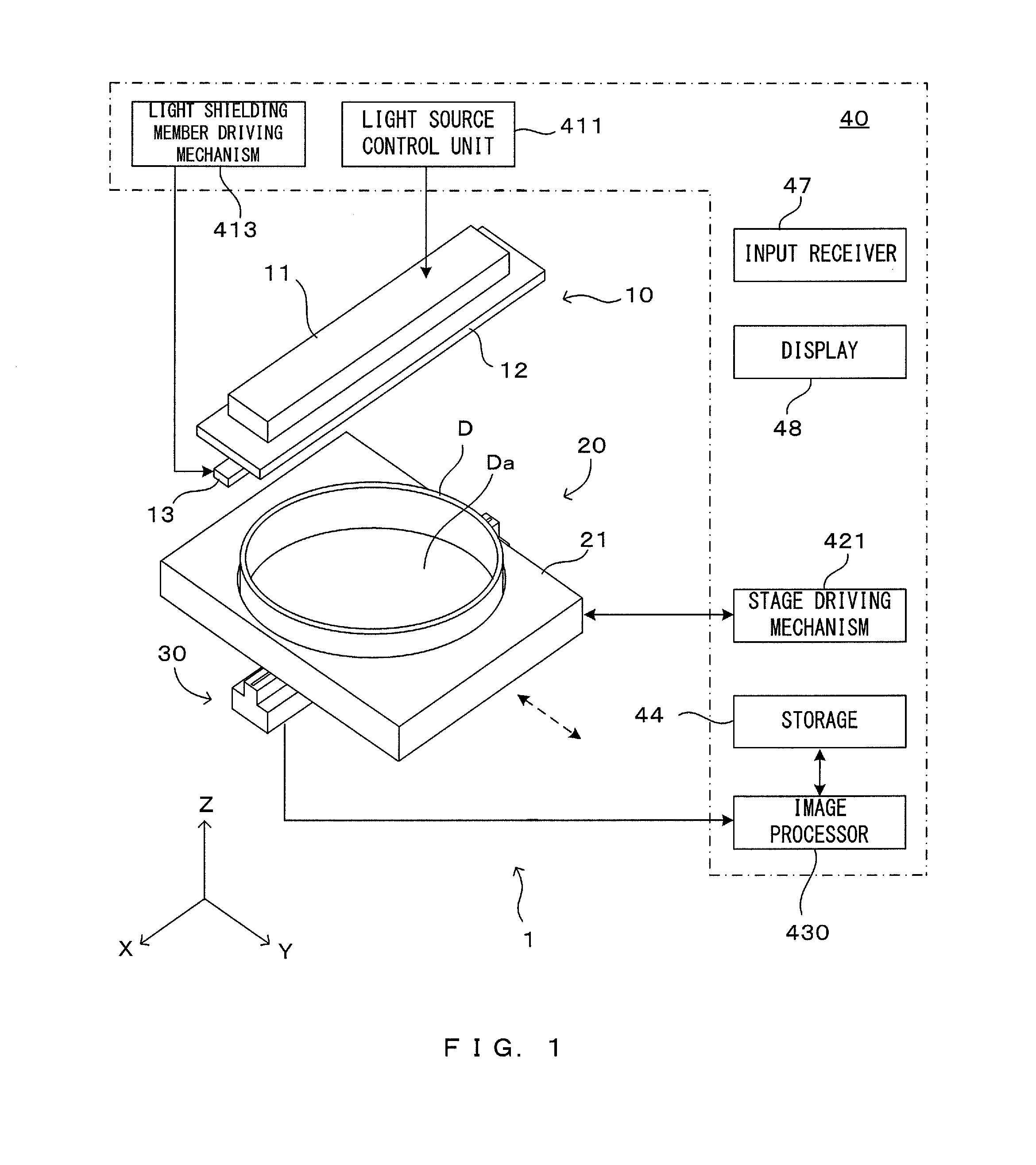
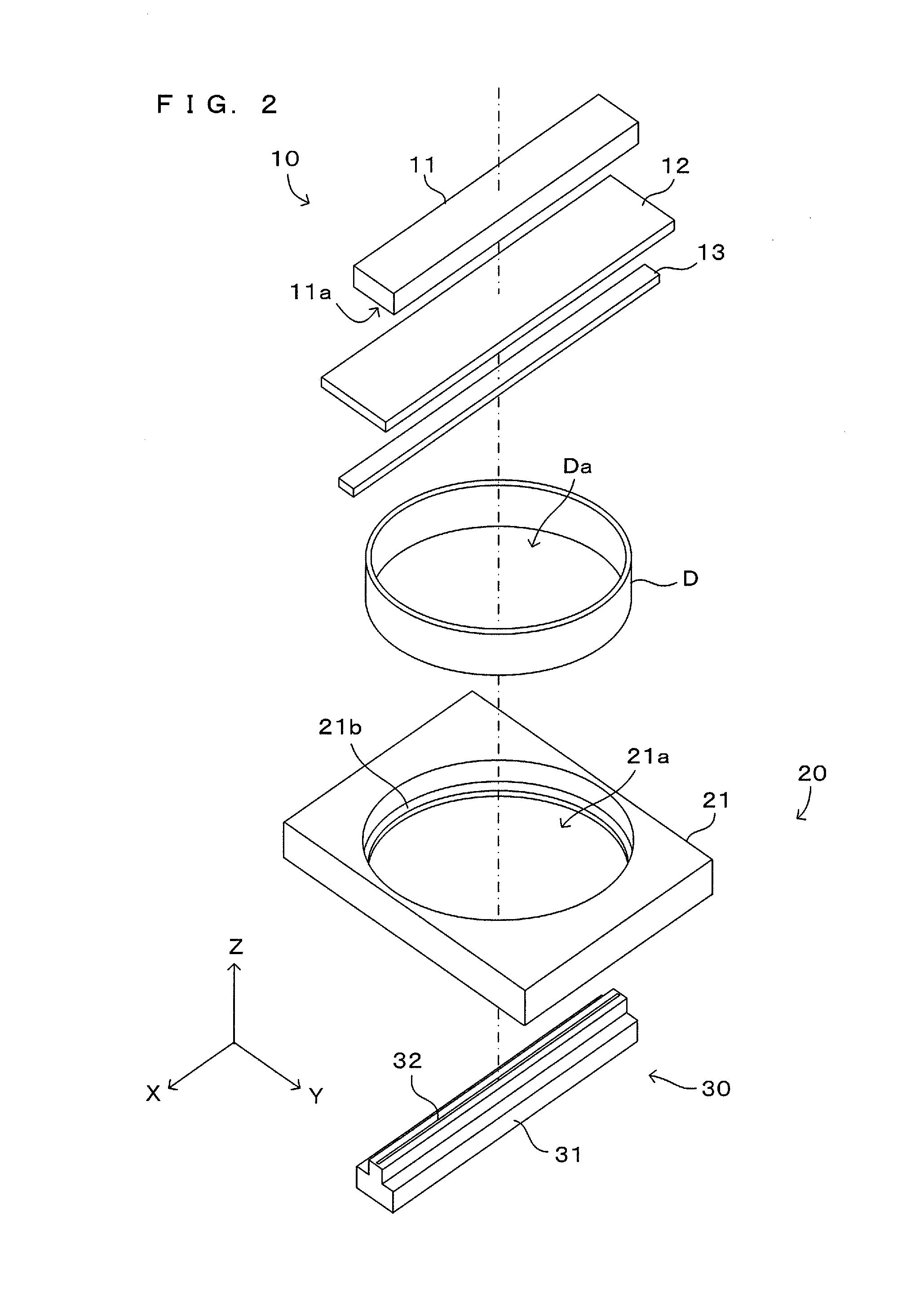
[0023]FIG. 1 is a view showing a main configuration of a first embodiment of an imaging apparatus according to this invention. FIG. 2 is an exploded perspective view of the imaging apparatus of FIG. 1. An XYZ orthogonal coordinate system is set as shown in FIG. 1 for the following description. Here, an XY plane represents a horizontal plane and a Z axis represents a vertical axis.

[0024]This imaging apparatus 1 includes a holding unit 20 for holding a shallow cell culture dish (hereinafter, referred to merely as “dish”) D for carrying a biological sample as an imaging object substantially in a horizontal posture. An illumination unit 10 for illuminating the sample and an imaging unit 30 are respectively arranged above and below the holding unit 20, and a control unit 40 is provided to control the operation of each of these units. In FIG. 1, a supporting mechanism, a housing and the like for fixing each unit are not shown to clearly show the internal structure of the apparatus.

[0025]A...

second embodiment

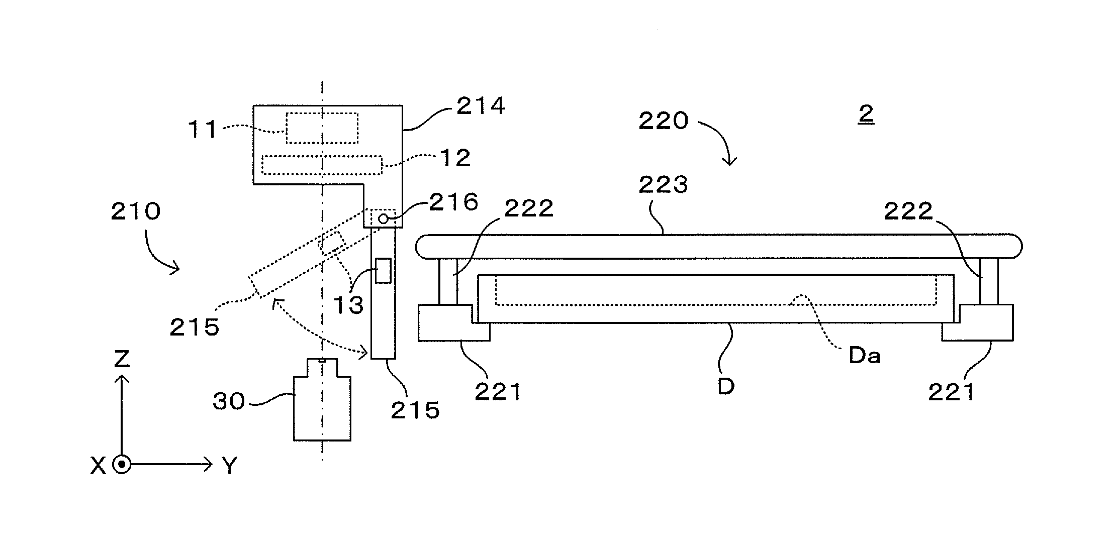
[0062]Next, a second embodiment of the imaging apparatus according to this embodiment is described. In the imaging apparatus 1 of the above first embodiment, the light shielding member driving mechanism 413 is provided to move the light shielding member 13 between the light shielding position Pa and the retracted position Pb. Contrary to this, the imaging apparatus of the second embodiment described next enables a light shielding member to be positioned without providing a driving mechanism for moving the light shielding member.

[0063]FIGS. 6A to 6C are views showing a main configuration of the second embodiment of the imaging apparatus according to this invention. Note that parts different from the imaging apparatus 1 of the first embodiment are mainly shown in FIGS. 6A to 6C. Each component provided in the first embodiment is similarly provided and similarly operates in this embodiment unless otherwise specified. Further, the components having the same functions as in the first emb...

third embodiment

[0069]Next, a third embodiment of the imaging apparatus according to this invention is described. An apparatus configuration of the third embodiment may be the same as that of the first or second embodiment. A feature of this embodiment is to optimize an illumination condition, i.e. to adjust the light quantity of the illumination unit before the imaging operation of FIG. 5 is performed.

[0070]FIGS. 7A and 7B are drawings showing the principle of an illumination unit adjustment in the third embodiment. More specifically, FIG. 7A is a view showing factors affecting an illumination light quantity, and FIG. 7B is a graph illustrating a distributed state of gradation values when the same sample was imaged under various illumination conditions. As described above, in the embodiments of the imaging apparatus according to the invention, the ratio of the transmitted light components and the scattered light components to be incident on the imaging unit 30 changes according to the values of th...


PUM

PropertyMeasurementUnit
thicknessaaaaaaaaaa
thicknessaaaaaaaaaa
angleaaaaaaaaaa

Abstract

An imaging apparatus for imaging a two-dimensional image of an imaging object comprises a holder which holds a sample container carrying a biological sample as the imaging object on a carrying surface, a light emitting part which emits light toward the carrying surface, an imager which includes a strip-like light receiving part, receives the light incident on the light receiving part and thereby images an image of a strip-like region of the carrying surface, a strip-like light shield which shields a part of light emitted from the illuminator toward the strip-like region, and a mover which integrally and relatively moves the light emitting part, the light receiving part and the light shield with respect to the sample container.

Description

CROSS REFERENCE TO RELATED APPLICATION[0001]The disclosure of Japanese Patent Application No. 2013-177573 filed on Aug. 29, 2013 including specification, drawings and claims is incorporated herein by reference in its entirety.BACKGROUND OF THE INVENTION[0002]1. Field of the Invention[0003]This invention relates to an imaging apparatus and an imaging method for imaging a biological sample carried in a sample container.[0004]2. Description of the Related Art[0005]In medical or bio-scientific experiments, biological samples such as specimen tissues extracted from biological bodies or cells cultured in liquids or gel-like media are observed and measured. Conventionally, it has been a general practice to stain a biological sample with an appropriate dye matching an imaging purpose and image the biological sample with enhanced visibility. However, to avoid damage to a sample, the sample needs to be imaged without being stained in some cases. A configuration example of an imaging apparatus...

Claims


Application Information

Patent Timeline
Patent Type & Authority Applications(United States)
IPC IPC(8): G01N21/25
CPCG01N21/255G01N2201/064G01N2201/0668G01N21/47
Inventor MORIWAKI, SANZOFUJIMOTO, HIROKI
Owner DAINIPPON SCREEN MTG CO LTD
Why Eureka
Try Eureka