

Bodily worn multiple optical sensors heart rate measuring device and method
- Summary
- Abstract
- Description
- Claims
- Application Information
AI Technical Summary
Benefits of technology
Problems solved by technology
Method used
Image

Examples
Embodiment Construction
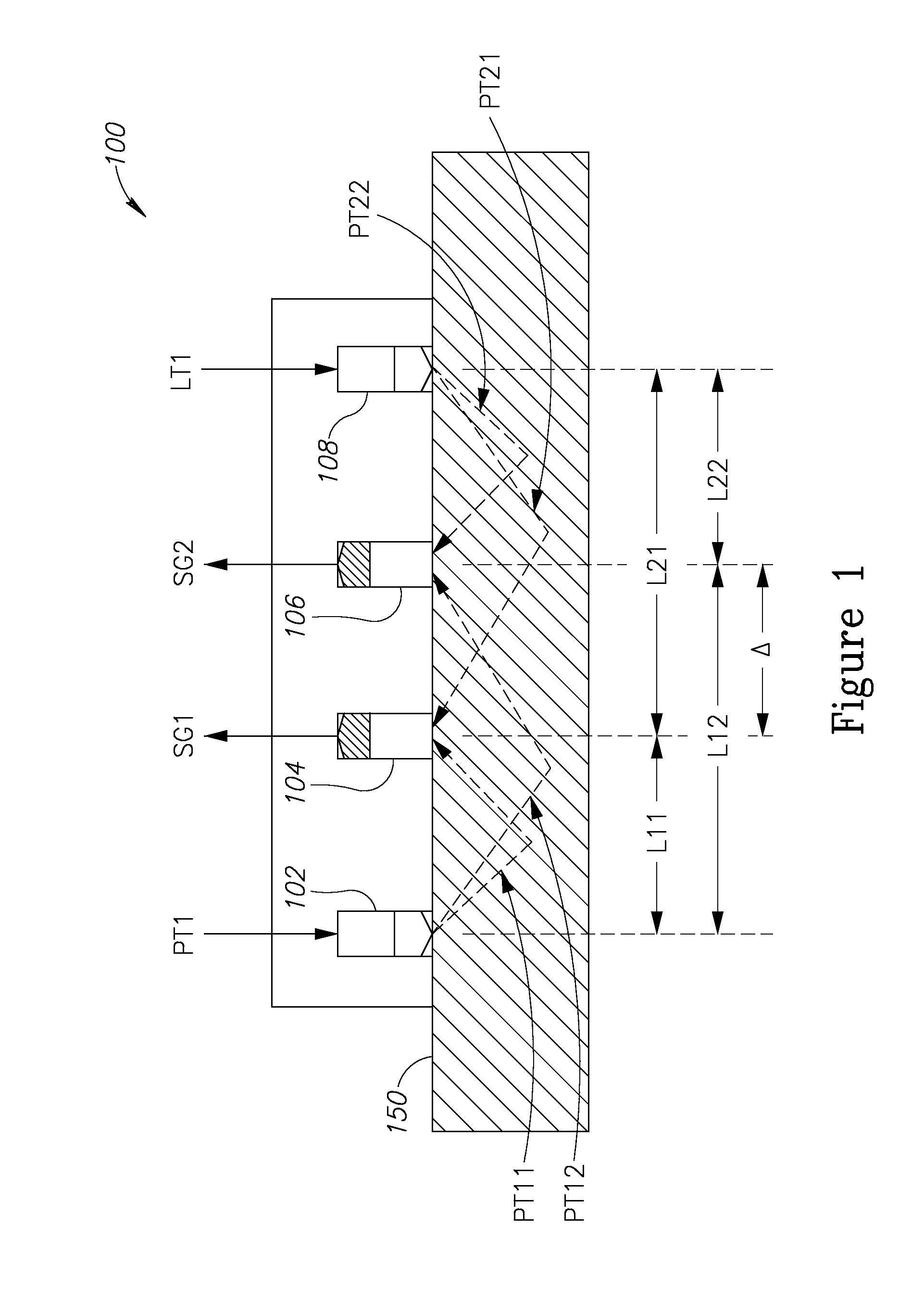
[0008]The present invention, in embodiments thereof, addresses the sensitivity of PPG sensors to movements which may cause undesired noise and inaccurate heart rate measurement. Embodiments of the present invention provide a multi sensor approach that together with a validation process that takes into account the ratio of the incoming signals provides a far more robust PPG sensor for heart rate measurement purposes than PPG based sensors that are currently available.
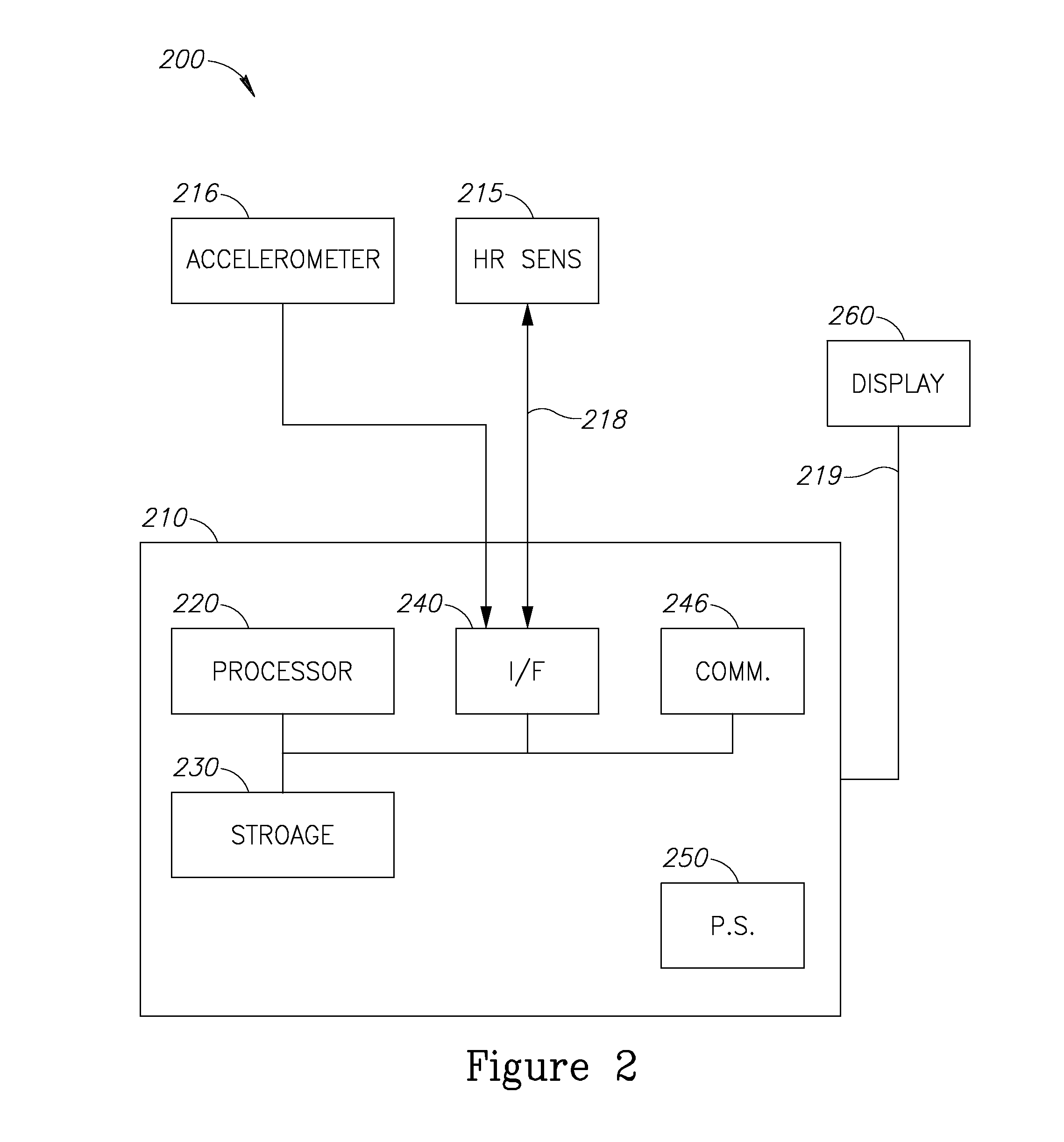
[0009]According to some embodiments, an accelerometer may be further used herein for enhancing the quality and the correctness of the heart rate measuring of the aforementioned heart rate measuring device. The use of an accelerometer may be advantageous in at least three of the following manners: to measure degree of activity of the person wearing the sensing device, to detect a rate of change in that activity and to derive a transfer function of the person wearing the heart rate measuring device. A processor may then us...
PUM
 Abstract
Description
Claims
Application Information