Inkjet printer and printing method
a printing method and printer technology, applied in the direction of printing, other printing apparatus, etc., can solve the problems of unsatisfactory, uneven density, deterioration of images, etc., and achieve the effect of reducing increasing the color density of pixels, and easy visual confirmation of dots
- Summary
- Abstract
- Description
- Claims
- Application Information
AI Technical Summary
Benefits of technology
Problems solved by technology
Method used
Image

Examples
first embodiment
1. FIRST EMBODIMENT
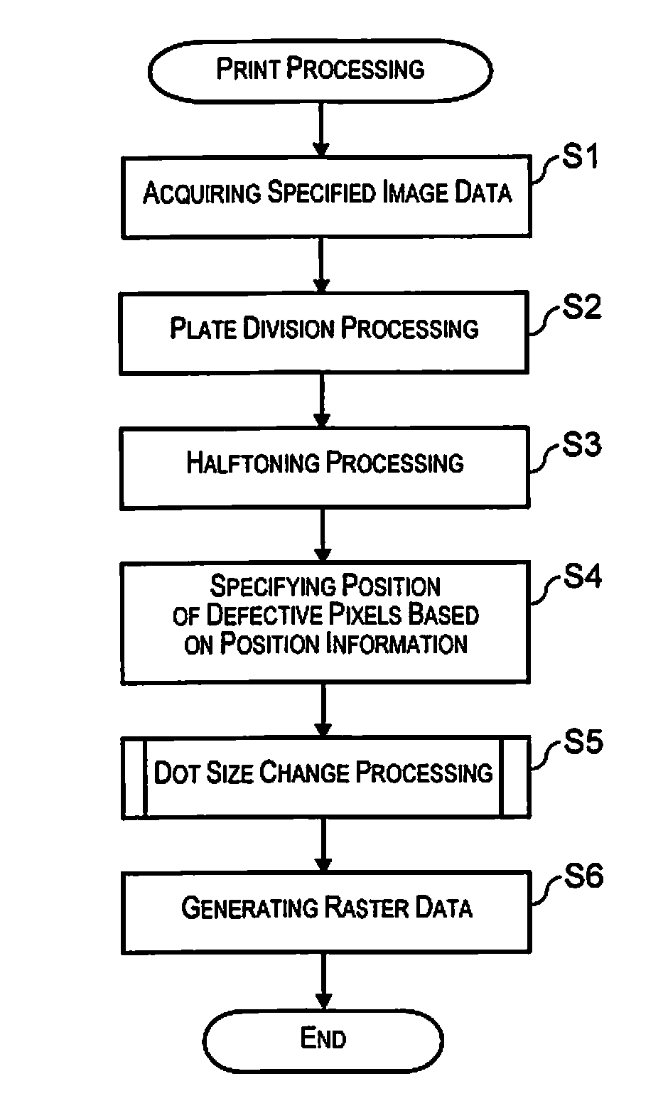
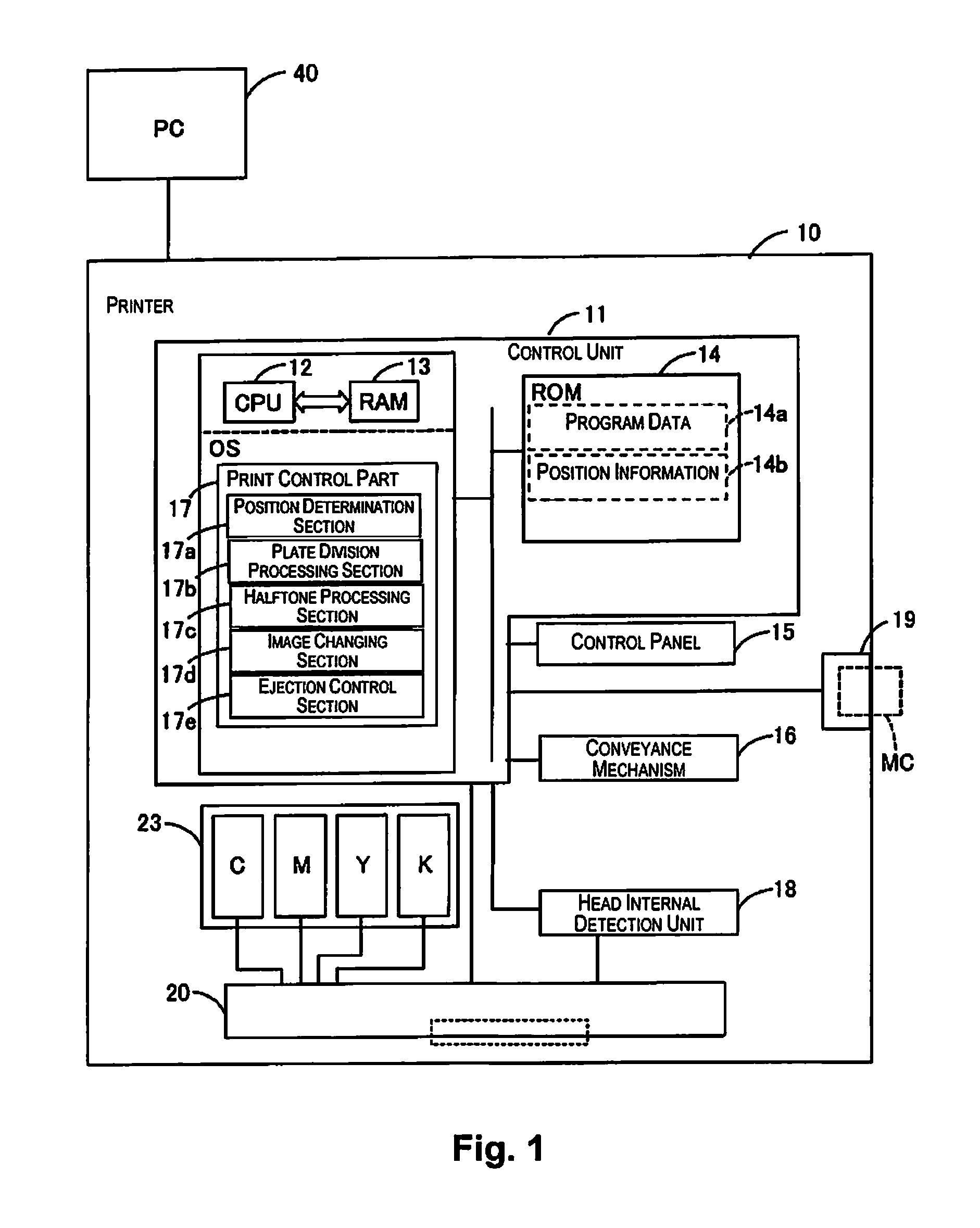
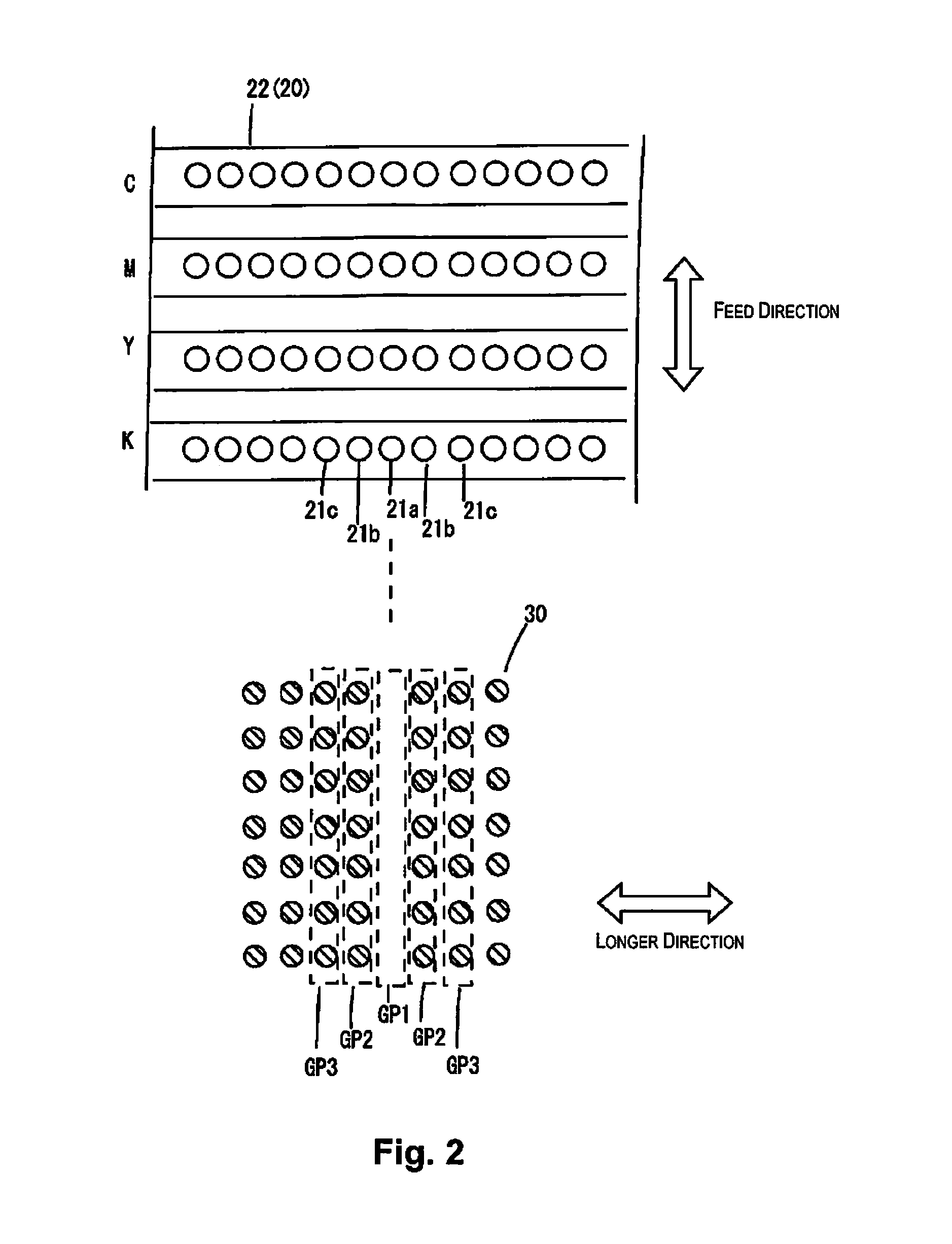
[0055]FIG. 1 schematically shows a hardware configuration and a software configuration according to the present embodiment. FIG. 2 exemplifies a part of each nozzle array in each of CMYK in an ejecting hole face 22 (surface that openings of a nozzle 21 are formed) of a print head 20, and dots on a print substrate printed by the nozzle arrays.
[0056]In FIG. 1, a PC (personal computer) 40 and a printer 10 are shown. The printer 10 corresponds to an inkjet printer. A system including the PC 40 and the printer 10 may be counted as a printing device. The printer 10 is provided with a control unit 11 to control a print processing. In the control unit 11, a CPU 12 executes a firmware to control the own device by developing program data 14a, which is stored in a ROM 14, etc., in a RAM 13 and performing operation in accordance with the program data 14a under the OS. The firmware is a program to execute functions of a print control section 17, etc. by the CPU 12.
[0057]Furthe...
second embodiment
2. SECOND EMBODIMENT
[0112]In the second embodiment, the configuration that switches between a dot size change and a density correction depending on the color density of an image is different from the first embodiment. In a case of an image expressing light gradation, etc. which is low color density, when the dot size changes to larger, the dots are noticeable, that is, the graininess is deteriorated. Therefore, for such image, the dot size change is not performed, and the density correction is performed so that the dot omission becomes less noticeable.
[0113]In the second embodiment, the pixels in the designated image data that are printed by the defective nozzle are defined as defective pixels P1, and the pixels, which are the first pixel adjacent to the defective pixels P1 in the designated image data, are disclosed as the second pixels P2. In the same manner, the pixels, which are the second pixel adjacent to the defective pixels P1 in the designated image data, are disclosed as t...
third embodiment
3. THIRD EMBODIMENT
[0163]Up to here, it was explained to presume that the printer 10 is provided with the print head 20 as a head for line printer. However, the printer 10 is provided with the print head 20 being movable in the scanning axis direction, which is defined in a direction intersecting with the aforementioned feed direction, and that is, it may be a serial printer.
[0164]FIG. 18 is a diagram showing the print head 20 as a head for serial printer.
[0165]In the print head 20, a nozzle array of each color of C, M, Y, K is provided with a plurality of nozzles 21 that is respectively arranged in the feed direction. Therefore, in the third embodiment, the second nozzles 21b, which are positioned adjacent to the defective nozzle 21a, are positioned adjacent to the defective nozzle 21a in the feed direction. Also, the third nozzles 21c, which are the first pixel adjacent to the second nozzles 21b, are positioned adjacent to the second nozzles 21b in the feed direction.
[0166]With su...
PUM
 Abstract
Description
Claims
Application Information
 - R&D
- Intellectual Property
- Life Sciences
- Materials
- Tech Scout
- Unparalleled Data Quality
- Higher Quality Content
- 60% Fewer Hallucinations
Browse by: Latest US Patents, China's latest patents, Technical Efficacy Thesaurus, Application Domain, Technology Topic, Popular Technical Reports.
© 2025 PatSnap. All rights reserved.Legal|Privacy policy|Modern Slavery Act Transparency Statement|Sitemap|About US| Contact US: help@patsnap.com