Eureka AIR delivers breakthrough ideas for toughest innovation challenges, trusted by R&D personnel around the world.

System and method for illuminating a headphone to indicate volume and/or beat

a headphone and volume indicator technology, applied in the field of headphones, can solve the problems of difficult to determine if the user can hear external noise, comments or questions, and third-party observers cannot determine if the user wearing the headset is listening to an audio signal or if the headset is used,

Inactive Publication Date: 2015-03-12
STEENKAMP SHANE CAMERON
View PDF4 Cites 18 Cited by
  • Summary
  • Abstract
  • Description
  • Claims
  • Application Information

AI Technical Summary

Benefits of technology

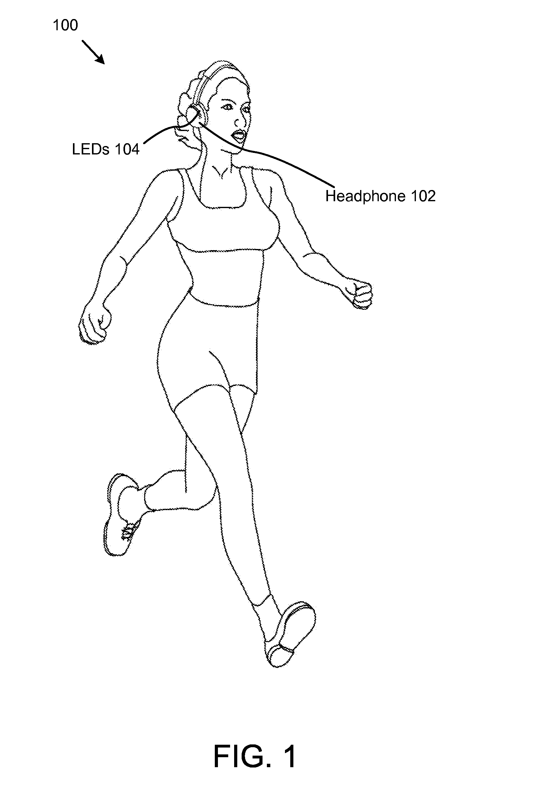
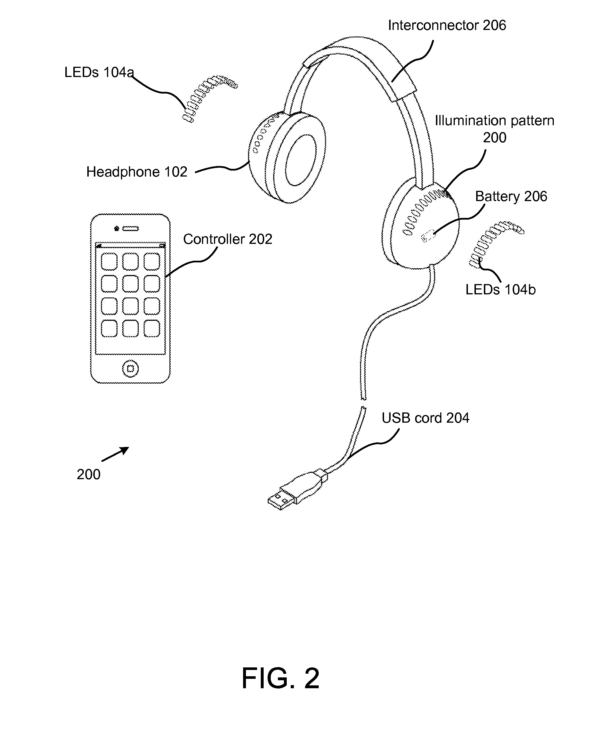
The present invention is a system for illuminating a headphone that uses light emitting diodes to indicate the volume and rhythm of the audio signal emitted from the headphone. The illumination pattern is synchronized with the audio signal to provide an instantaneous, graphical indication. The LEDs used in the system have advantages such as lower energy consumption, longer lifetime, improved physical robustness, smaller size, and faster switching. The system can be controlled remotely and can join with portable electronic devices. The LEDs generate heat, which needs to be dissipated, and a heat sink is used for this purpose. Overall, the present invention provides a unique and innovative way to enhance the user experience of headphones.

Problems solved by technology

Often, third-party observers cannot determine if a user wearing a headset is listening to an audio signal or if the headset is silent.
This is because the sound emitting from the headphones is indiscernible by the observer.
Consequently, it is often difficult to determine if the user can hear any external noises, comments or questions.
In view of the foregoing, it is clear that these traditional headphone illuminating systems and methods are not perfect and leave room for more optimal approaches.
In this manner, the color of the illumination may be interchanged, and damaged LEDs may be replaced.

Method used


Image

  • System and method for illuminating a headphone to indicate volume and/or beat
  • System and method for illuminating a headphone to indicate volume and/or beat
  • System and method for illuminating a headphone to indicate volume and/or beat

Examples


Embodiment Construction

[0028]Reference throughout this specification to “one embodiment,”“an embodiment,” or similar language means that a particular feature, structure, or characteristic described in connection with the embodiment is included in at least one embodiment of the present invention. Thus, appearances of the phrases “in one embodiment,”“in an embodiment,” and similar language throughout this specification may, but do not necessarily, all refer to the same embodiment.

[0029]Furthermore, the described features, structures, or characteristics of the invention may be combined in any suitable manner in one or more embodiments. In the following description, numerous specific details are provided, such as examples of programming, software modules, user selections, network transactions, database queries, database structures, hardware modules, hardware circuits, hardware chips, etc., to provide a thorough understanding of embodiments of the invention. One skilled in the relevant art will recognize, howe...


PUM


Abstract

A system, apparatus and method for illuminating a headphone to indicate the volume and / or rhythm of an audio signal emitting from the headphone through a flashing illuminated pattern of light emitting diodes visible to an observer. The pattern and synchronization of the illumination pattern provides an instantaneous, graphical indication of the volume, rhythm, intensity, and frequency of the audio signal. The invention includes a headphone. A plurality of light emitting diodes (LEDs) operably attach to the headphone(s). The LEDs form a pattern in, or on, the headphone(s) that is efficacious for prominently displaying the illumination. Various pattern shapes can be utilized. The illumination produced by the LEDs is efficacious for signaling the different variances of the audio signal. A USB cable may provides power and data signals for the headphone(s). A battery may provide power. A heat sink helps dissipate heat from the LEDs.

Description

FIELD OF THE INVENTION[0001]This invention relates to headphones, and more particularly relates to a method and system for illuminating a headphone as a function of a volume and a rhythm for an audio signal.BACKGROUNDDescription of the Related Art[0002]The following background information may present examples of specific aspects of the prior art (e.g., without limitation, approaches, facts, or common wisdom) that, while expected to be helpful to further educate the reader as to additional aspects of the prior art, is not to be construed as limiting the present invention, or any embodiments thereof, to anything stated or implied therein or inferred thereupon.[0003]By way of educational background, another aspect of the prior art generally useful to be aware of is that headphones may include a pair of small loudspeakers that are designed to be held in place close to a user's ears. Headphones either have wires for connection to a signal source such as an audio amplifier, radio, CD play...

Claims


Application Information

Patent Timeline
IPC IPC(8): H04R1/10
CPCH04R1/1041H04R1/1091H04R5/033H04R1/1016H04R1/10H04R1/1008
Inventor STEENKAMP, SHANE CAMERON
Owner STEENKAMP SHANE CAMERON
Why Eureka
Eureka Blog
Learn More