Portable Wireless Mesh Device Having Improved Antenna System

a wireless mesh and antenna system technology, applied in the field of wireless mesh networks, can solve the problems of limiting the amount of power that a node can use to transmit, the mesh router is typically fixed in place or has extremely limited mobility, and the fixed wireless mesh network, so as to save significant time and cost in setting up the network

Active Publication Date: 2015-03-12
OLEA NETWORKS
View PDF8 Cites 13 Cited by
  • Summary
  • Abstract
  • Description
  • Claims
  • Application Information

AI Technical Summary

Benefits of technology

[0016]According to another embodiment, each mobile mesh device may include a plurality of end-fed dipole antennas, which are completely enclosed within a housing of the mobile mesh device and configured to forward network traffic. At least one of the end-fed dipole antennas may include a pin (referred to herein as a channel selection pin), whose position can be adjusted up or down along an axis of the end-fed dipole antenna to change the resonant frequency of the end-fed dipole antenna. This pin enables a user or technician of the wireless mesh network to tune or set the frequency of substantially all mobile mesh devices within the wireless mesh network to a particular (e.g., less noisy) channel within the operating frequency band of the end-fed dipole antenna.
[0019]According to one embodiment, the channel selection pin may be coupled onto the transmission feed line via a compressive force. For example, the channel selection pin may comprise a stiff metal wire formed so as to include a wound section, which is configured to provide the compressive force, and which is terminated at each end with a wire element that extends away from the wound section. In some embodiments, a length of each of the wire elements may be approximately equal to one-quarter (¼) of a wavelength of the resonant frequency of the channel selection pin. In addition to providing a mechanism with which to easily tune the resonant frequency of the dipole antenna, the channel selection pin improves the antenna radiation pattern, reduces the number of side lobes and decreases the angle of radiation by providing a relatively high choking impedance to undesirable currents flowing on the exterior of the transmission feed line.
[0024]In some cases, it may be beneficial to mount the plurality of antennas in an inverted ground plane configuration. According to one embodiment, the upper compartment may be configured for attachment to a mounting structure, which is arranged at an elevated location above the lower compartment of the mobile mesh device. To achieve the inverted ground plane configuration, the upper compartment may be attached to the mounting structure, so that the common ground plane is positioned above the plurality of antennas. This provides the advantage of directing the antenna radiation back down towards the ground. In some embodiments, signal loss may be avoided or substantially reduced by configuring the mounting structure so that it may house or accommodate the one or more radio modules when the upper compartment is attached thereto.
[0027]In some embodiments, an action may be triggered by the identity and / or the location of the transmitting device. Exemplary actions that may be trigged include, but are not limited to, alerting a user to the identity and / or location of the transmitting device, logging the identity and / or location of the transmitting device, activating a camera to record video / audio at the location of the transmitting device, locking / unlocking a door, flipping a switch or valve, etc. As but one distinction over conventional wireless mesh networks, the mobile mesh device described herein provides RTLS services in a temporary and / or wireless mesh network without the need to first fingerprint or map the network coverage area. This saves significant time and cost in setting up the network, as site surveys and fingerprinting are not needed to accurately determine the location of transmitting devices within the wireless mesh network.

Problems solved by technology

However, at least in the case of many wireless networks, regulations limit the amount of power that a node can use to transmit.
One drawback of conventional wireless mesh networks is that the mesh routers are typically fixed in place or have extremely limited mobility, since they generally require a wired connection to either an external network and / or a power source.
This renders fixed wireless mesh networks, such as the one shown in FIG. 1, unsuitable for mobile mesh networking applications in which portability of the mesh routers is not only desired, but required to meet the needs of a given application.

Method used


Image

  • Portable Wireless Mesh Device Having Improved Antenna System
  • Portable Wireless Mesh Device Having Improved Antenna System
  • Portable Wireless Mesh Device Having Improved Antenna System

Examples


Embodiment Construction

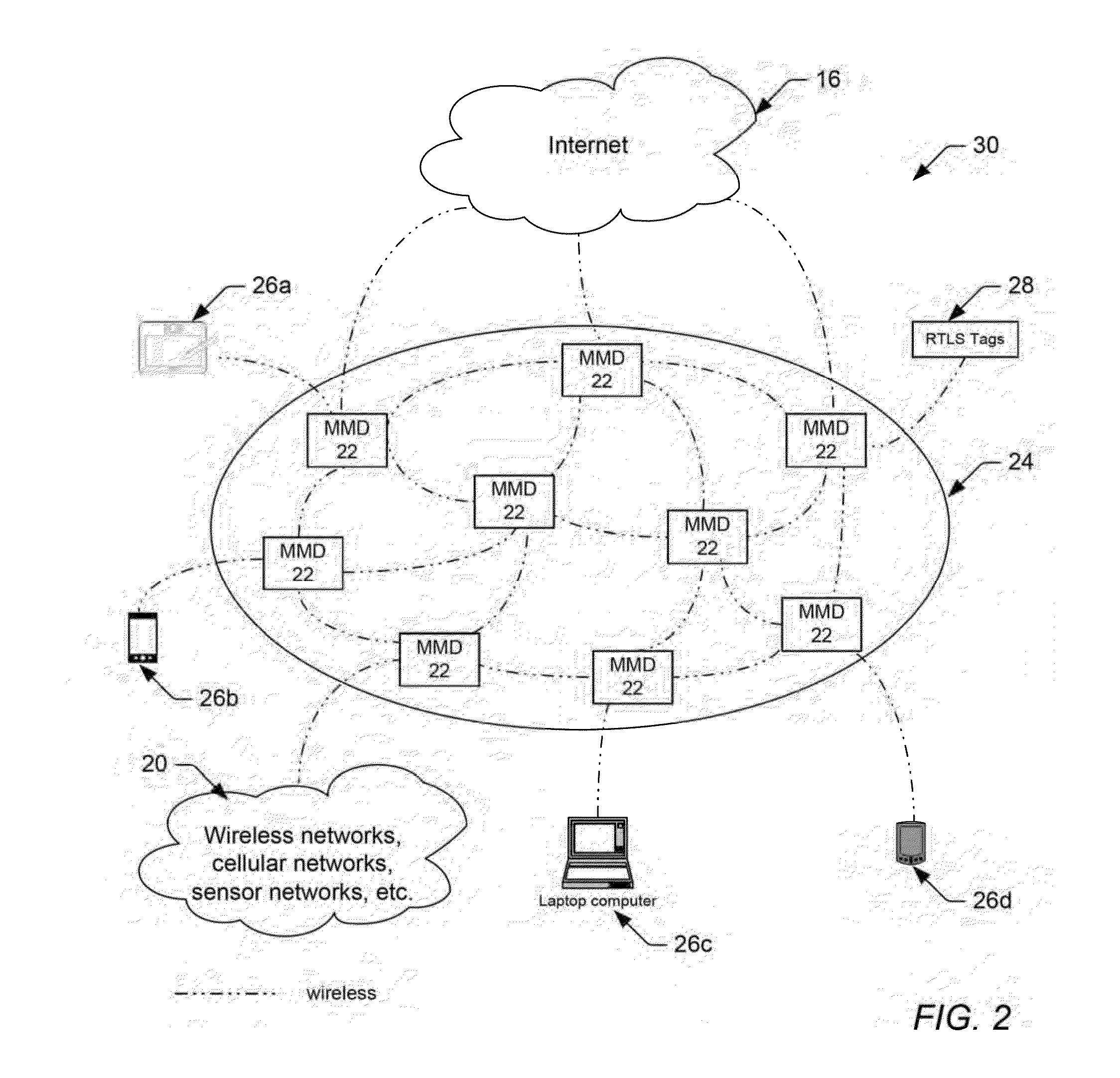
[0053]FIG. 2 illustrates an improved wireless mesh network 30 comprising a plurality of portable, self-contained wireless mesh devices 22 (referred to hereinafter as mobile mesh devices, or MMDs), which can be used to provide a temporary and / or rapidly deployable wireless mesh network. Similar to the wireless mesh routers (MRs) shown in FIG. 1, the mobile mesh devices 22 used within the wireless mesh network 30 of FIG. 2 provide a self-forming, self-configuring and self-healing network of mesh nodes. These nodes are organized in a mesh topology and create a wireless mesh backbone 24 that offers services to client devices 26, e.g., by providing wireless client access to the Internet 16, to other client devices 26, and to other wired or wireless networks 20 (which may include, but are not limited to, other mesh networks, other wireless networks, cellular networks, and sensor networks). Like the wireless mesh routers (MRs) shown in FIG. 1, the mobile mesh devices 22 shown in FIG. 2 uti...


PUM


Abstract

A wireless mesh network comprising a plurality of mobile mesh devices coupled as nodes in a mesh network topology is provided herein. Generally speaking, each mobile mesh device may be a portable, self-contained unit, which does not require network or power wiring to communicate network traffic between the nodes. According to one embodiment, the mobile mesh device may include a plurality of dipole antennas, which are enclosed within the mobile mesh device and configured to forward network traffic. At least one of the dipole antennas may be a frequency adjustable end-fed dipole antenna comprising a channel selection pin, which can be adjusted up or down along the dipole axis to change a resonant frequency of the dipole antenna. A method for setting or adjusting a resonant frequency of a frequency adjustable end-fed dipole antenna is also provided herein.

Description

PRIORITY CLAIM[0001]The present application claims priority to prior U.S. Application No. 61 / 876,875 filed Sep. 12, 2013.BACKGROUND OF THE INVENTION[0002]1. Field of the Invention[0003]The present invention generally relates to wireless mesh networks, and more particularly to a portable wireless mesh device that can be used to provide a temporary and / or rapidly deployable wireless mesh network.[0004]2. Description of the Related Art[0005]The following descriptions and examples are not admitted to be prior art by virtue of their inclusion within this section.[0006]Wireless communication networks have gained widespread use in recent years. Among the commonly used forms of wireless networks are those that implement versions of Institute of Electrical and Electronics Engineers (IEEE) standard 802.11 (Wi-Fi), IEEE standard 802.15 (Bluetooth) and IEEE standard 802.16 (WiMAX). In general, there is a push in the industry to continually improve both the range and reliability of such networks...

Claims


Application Information

Patent Timeline
Patent Type & Authority Applications(United States)
IPC IPC(8): H04B1/40H04W88/02H01Q9/18H04B15/00H04W4/02H04W4/029
CPCH04B1/40H01Q9/18H04W88/02H04B15/00H01Q1/246H01Q1/42H01Q9/14H01Q9/16H01Q9/22H01Q21/062H01Q5/307H01Q5/42H04M1/00G01S5/0289H04B1/3888H04L69/08H04W4/029H04W4/02H04L65/00
Inventor MACKIE, DAVID
Owner OLEA NETWORKS
Why Eureka
Try Eureka