
Systems, Apparatus and Methods for Sealing Perivalvular Leaks

a technology of perivalvular leakage and apparatus, applied in the field of replacement prosthetic valves, can solve the problems of suffusion and swelling (edema) of all legs, significant medical problems in legs, ankles and feet, and deficient closing properties

Active Publication Date: 2015-03-12
CORMATRIX CARDIOVASCULAR INC
View PDF7 Cites 5 Cited by
  • Summary
  • Abstract
  • Description
  • Claims
  • Application Information

AI Technical Summary

Benefits of technology

The invention is a device that can be used to seal leaks in a heart valve. It consists of a support member and an expandable member that can be positioned at the valve to seal the leaks. The device is designed to transition from a pre-deployment configuration to a post-deployment configuration. The technical effect of this invention is to provide a reliable and effective way to treat heart valve leaks.

Problems solved by technology

As discussed in detail below, since a majority of venous blood flow is against gravity while a person is standing, incompetent or destroyed venous valves can cause significant medical problems in the legs, ankles, and feet.
In the case of a stenosis, the native valve does not open properly, whereby insufficiency represents the opposite effect showing deficient closing properties.
Insufficiency of the inlet (atrioventricular) tricuspid valve to the right ventricle of the heart results in regurgitation of blood back into the right atrium, which, serving to receive blood flow returning in the veins from the entire body, then results, in turn, in suffusion and swelling (edema) of all the organs, most notably in the abdomen and extremities, insufficient forward conduction of blood flow from the right ventricle into the lungs causing compromise of pulmonary function, and ultimately pump failure of the right heart.
Insufficiency of vein function due to the incompetence or destruction of peripheral venous valves leads to acute then chronic swelling of the veins and their dependent lymphatics and tissues.
Medical conditions like high blood pressure, inflammatory and infectious processes often lead to stenosis and insufficiency.
The implantation of a prosthetic valve, including mechanical valves and bioprosthetic valves, requires a great deal of skill and concentration given the delicate nature of the native cardiovascular tissue and the spatial constraints of the surgical field.
There are numerous drawbacks and disadvantages associated with suturing a valve to host tissue.
A major disadvantage is the high risk of a perivalvular leak.
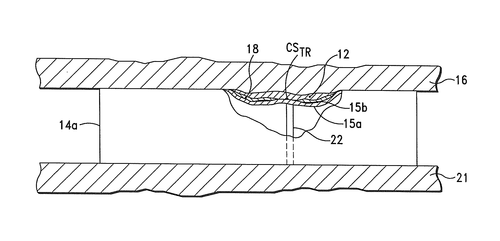
Perivalvular leaks are also often encountered during or after a cardiovascular valve replacement due to placement of the replacement valve over native valve leaflets, which are often calcified.

Method used


Image

  • Systems, Apparatus and Methods for Sealing Perivalvular Leaks
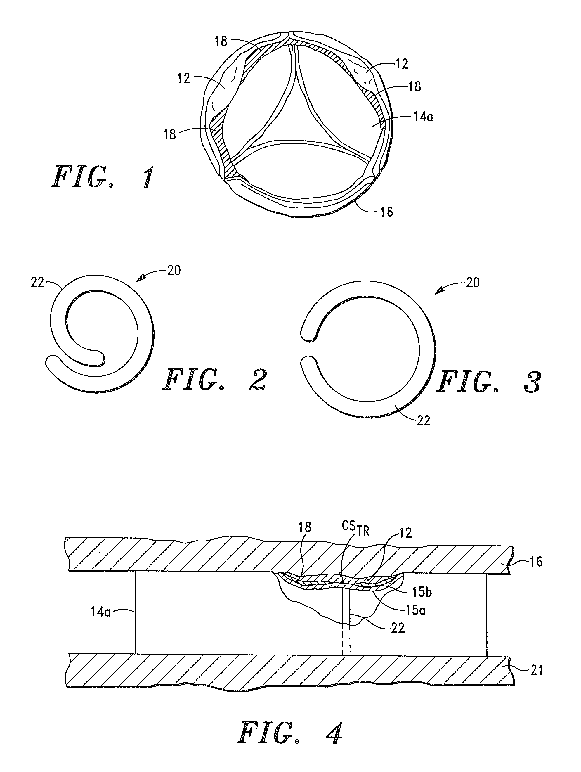
  • Systems, Apparatus and Methods for Sealing Perivalvular Leaks
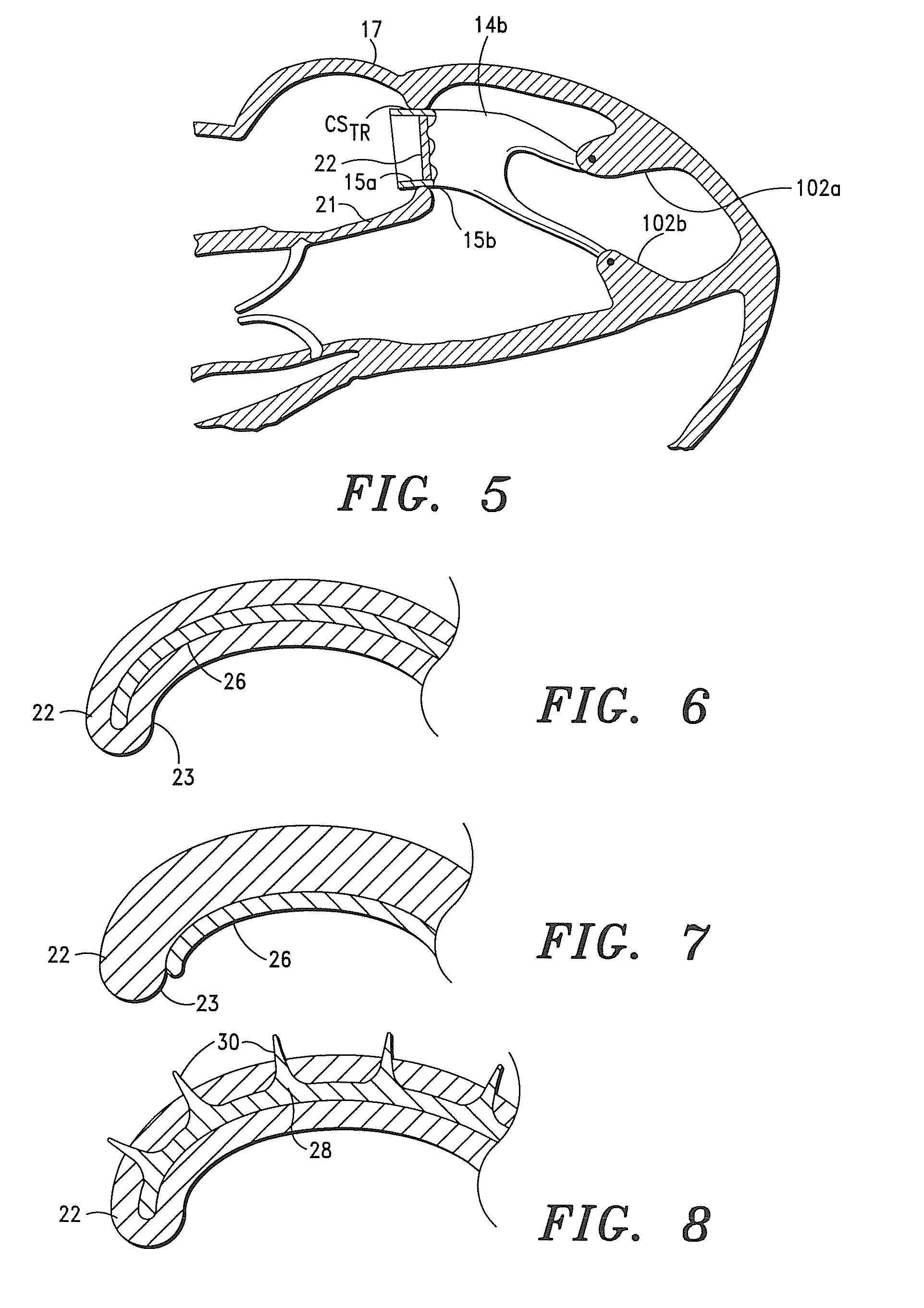
  • Systems, Apparatus and Methods for Sealing Perivalvular Leaks

Examples


Embodiment Construction

[0051]Before describing the present invention in detail, it is to be understood that this invention is not limited to particularly exemplified apparatus, systems, structures or methods as such may, of course, vary. Thus, although a number of apparatus, systems and methods similar or equivalent to those described herein can be used in the practice of the present invention, the preferred apparatus, systems, structures and methods are described herein.

[0052]It is also to be understood that the terminology used herein is for the purpose of describing particular embodiments of the invention only and is not intended to be limiting.

[0053]Unless defined otherwise, all technical and scientific terms used herein have the same meaning as commonly understood by one having ordinary skill in the art to which the invention pertains.

[0054]Further, all publications, patents and patent applications cited herein, whether supra or infra, are hereby incorporated by reference in their entirety.

[0055]As u...


PUM


Abstract

An expandable member that is configured to engage an interior region of a prosthetic valve and capable of transitioning from a pre-deployment configuration at a pre-deployment temperature, where the expandable member is capable of being positioned in the valve at an interior valve region when the valve is disposed in a cardiovascular structure, to a post-deployment configuration when the expandable member is subjected to cardiovascular tissue temperature, where an outer surface region of the valve proximate the interior valve region is placed in intimate contact with host cardiovascular tissue of the cardiovascular structure at a first position and seals perivalvular leaks present at the first cardiovascular structure position.

Description

CROSS-REFERENCE TO RELATED APPLICATIONS[0001]This application claims priority to U.S. Provisional Application No. 61,876,540, filed on Sep. 11, 2013.FIELD OF THE INVENTION[0002]The present invention generally relates to replacement prosthetic valves. More particularly, the present invention relates to an apparatus and method for sealing perivalvular leaks; particularly, during or after a cardiovascular valve replacement.BACKGROUND OF THE INVENTION[0003]As is well known in the art, the human heart has four valves that control blood flow circulating through the human body. On the left side of the heart is the mitral valve, located between the left atrium and the left ventricle, and the aortic valve, located between the left ventricle and the aorta. Both of these valves direct oxygenated blood from the lungs into the aorta for distribution through the body.[0004]The tricuspid valve, located between the right atrium and the right ventricle, and the pulmonary valve, located between the r...

Claims


Application Information

Patent Timeline
Patent Type & Authority Applications(United States)
IPC IPC(8): A61F2/24
CPCA61F2/2463A61F2/2412A61F2250/0069
Inventor MATHENY, ROBERT G.
Owner CORMATRIX CARDIOVASCULAR INC
Learn More