
Method for cutting toughened glass plate

Inactive Publication Date: 2015-03-19
HAMAMATSU PHOTONICS KK +1
View PDF5 Cites 55 Cited by
  • Summary
  • Abstract
  • Description
  • Claims
  • Application Information

AI Technical Summary

Benefits of technology

The present invention provides a method for cutting strengthened glass sheets using laser light. The method can distinguish between cases where the glass sheets are divided without applying an external force and cases where they are divided by applying an external force. The internal reforming process helps to achieve precise and high-quality cuts.

Problems solved by technology

In the above-described method, the formation of the scribe line leads to the generation of a number of fine cracks on the cut edge surface of the strengthened glass sheet.
As a result, there has been a problem of insufficient strength at a cut edge portion (so-called edge strength) in spite of the use of the strengthened glass sheet.

Method used


Image

  • Method for cutting toughened glass plate
  • Method for cutting toughened glass plate
  • Method for cutting toughened glass plate

Examples


embodiment 1

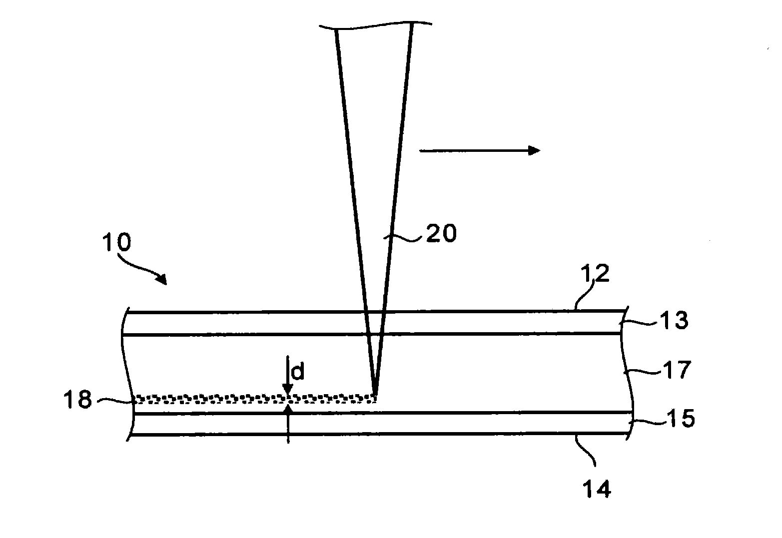
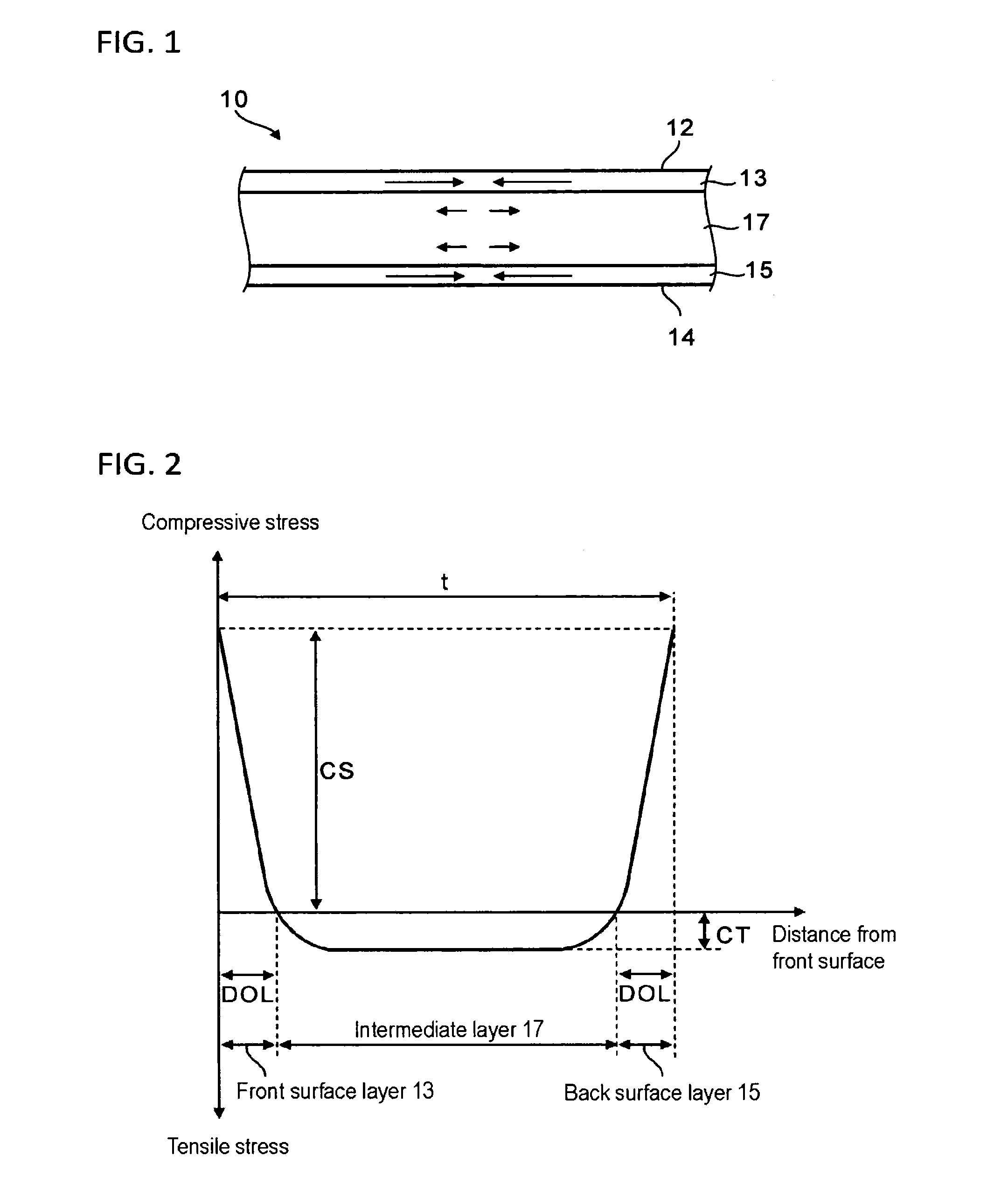
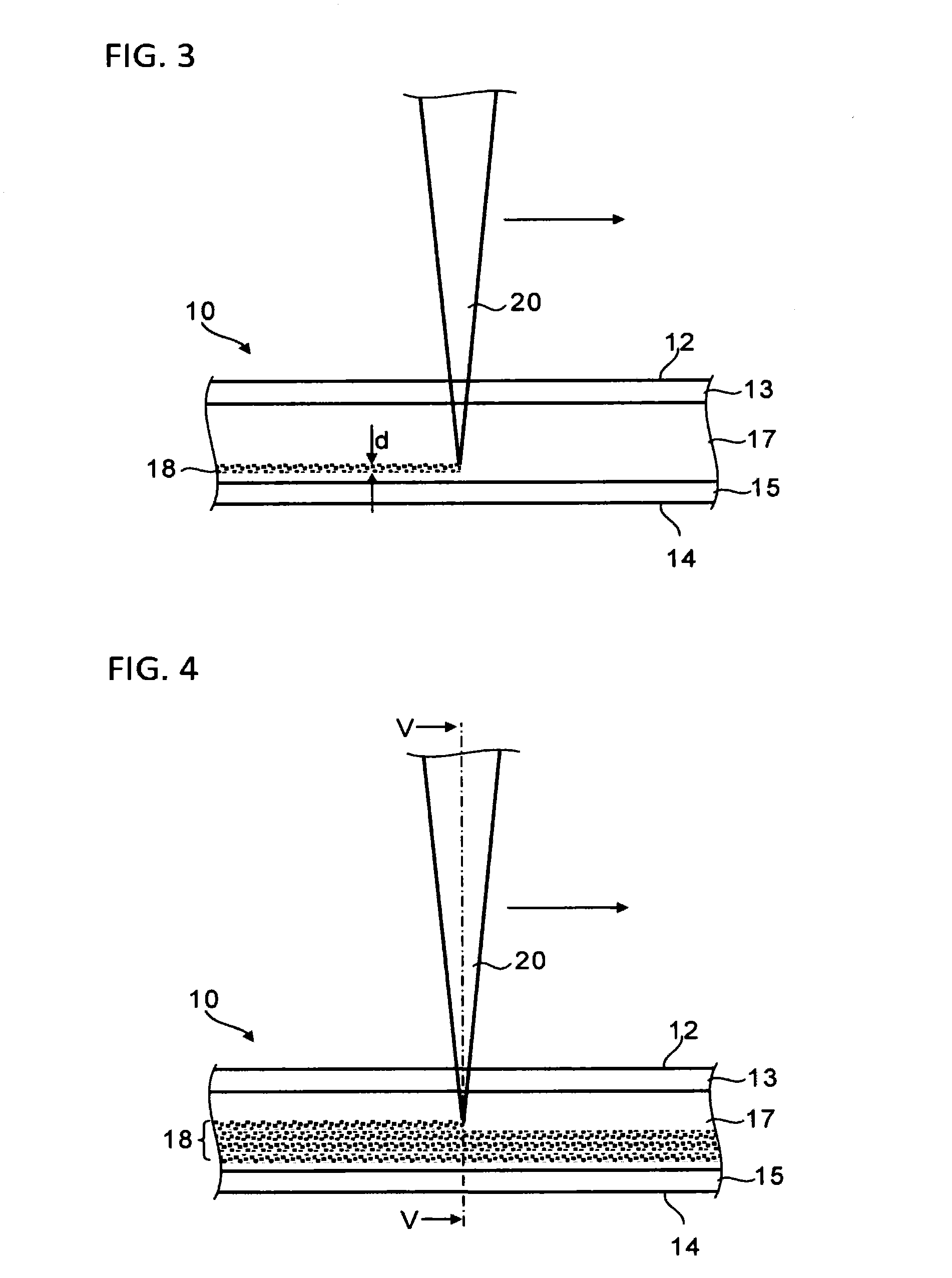
[0046]First, the structure of a strengthened glass sheet and a method for cutting a strengthened glass sheet using internal reforming through laser light will be described with reference to FIGS. 1 to 5.

[0047]The structure of the strengthened glass sheet will be described with reference to FIGS. 1 and 2. FIG. 1 is a cross-sectional view of a strengthened glass sheet 10 before irradiation of laser light. In FIG. 1, the direction of an arrow indicates an acting direction of a residual stress, and the size of the arrow indicates the intensity of the stress. As illustrated in FIG. 1, the strengthened glass sheet 10 includes a front surface layer 13, a back surface layer 15, and an intermediate layer 17 provided between the front surface layer 13 and the back surface layer 15. In the front surface layer 13 and the back surface layer 15, a compressive stress remains due to the following air-quenching strengthening method or a chemical strengthening method. In addition, as a counteraction ...

example 1

[0081]In Example 1, the scanning of laser light irradiation was repeated on seven kinds of chemically strengthened glass sheet samples until the samples were divided, and the widths of the reformed regions at the time of the samples being divided were measured as the critical widths dc of the reformed regions.

[0082]FIG. 9 is a table describing the characteristics values and cutting results of the strengthened glass sheet. Specifically, from the left column, the table sequentially describes sample numbers, the thicknesses t (mm) of the strengthened glass sheets, the thicknesses DOL (mm) of the front surface layers and the back surface layers, the surface compressive stresses CS (MPa), the internal tensile stresses CT (MPa), the number of times of the scanning (SCAN TIMES), and the critical widths dc (mm) of the reformed regions.

[0083]The internal tensile stress CT of the strengthened glass sheet was measured by measuring the surface compressive stress CS and the thicknesses DOL of th...


PUM

PropertyMeasurementUnit
Thicknessaaaaaaaaaa
Thicknessaaaaaaaaaa
Distanceaaaaaaaaaa

Abstract

A method for cutting a strengthened glass sheet according to a first embodiment of the present invention includes: a step of collecting and scanning laser light in an intermediate layer, thereby forming a first reformed region along a first cutting-scheduled line; and a step of applying an external force to propagate a crack from the first reformed region as a start point in a thickness direction of the strengthened glass sheet, thereby dividing the strengthened glass sheet. In the step of forming the first reformed region, a width d1 (mm) of the first reformed region in the thickness direction is set to d1<2×10³×Kc2 / {π×(CT)2} based on a fracture toughness Kc (MPa·√m) of the strengthened glass sheet and the tensile stress CT (MPa) remaining in the intermediate layer.

Description

TECHNICAL FIELD[0001]The present invention relates to a method for cutting a strengthened glass sheet, and particularly to a method for cutting a strengthened glass sheet using internal reforming through laser light.BACKGROUND ART[0002]In a portable device such as a mobile phone or a personal data assistance (PDA), a glass sheet is used as a cover or substrate of a display. In response to the demand for thickness reduction and weight reduction of the portable device, a strengthened glass sheet having high strength has been used as the glass sheet in order to reduce the thickness and weight. The strengthened glass sheet includes a front surface layer in which a compressive stress remains and a back surface layer in which a compressive stress remains, and an intermediate layer formed between the front surface layer and the back surface layer in which a tensile stress remains.[0003]Generally, the strengthened glass sheet is cut by mechanically forming a scribe line on the main surface ...

Claims


Application Information

Patent Timeline
IPC IPC(8): B23K26/00C03B33/02
CPCC03B33/0222B23K26/0057C03B33/033C03B33/04Y02P40/57B23K26/53
Inventor KAWAGUCHI, DAISUKENAGASAWA, IKUO
Owner HAMAMATSU PHOTONICS KK
Learn More