Microfluidic organ assist device incorporating boundary layer disrupters

a technology of microfluidic organs and assist devices, which is applied in the direction of membranes, other chemical processes, multi-stage water/sewage treatment, etc., can solve the problems of inconvenient and expensive, extending treatment time or flow rate, and achieving higher dialysis efficiency. , to achieve the effect of increasing the dialysis efficiency, prolonging the treatment time or flow rate, and increasing the complications and problems of patient safety and quality of li

Active Publication Date: 2015-03-19
JOHNSON & JOHNSON INNOVATION
View PDF5 Cites 9 Cited by
  • Summary
  • Abstract
  • Description
  • Claims
  • Application Information

AI Technical Summary

Benefits of technology

[0003]According to one aspect of the disclosure, a microfluidic device includes a first layer defining a first channel therein. The microfluidic device also includes a second layer defining a second channel therein. The second channel overlaps the first channel along a substantial portion of the length of the first channel. A membrane separates the first channel from the second channel. The device also includes a protein gel ...

Problems solved by technology

Previous methods of achieving higher dialysis efficiencies, such as extending treatment time or flow rates, are inconvenient and expensive and can ...

Method used


Image

  • Microfluidic organ assist device incorporating boundary layer disrupters
  • Microfluidic organ assist device incorporating boundary layer disrupters
  • Microfluidic organ assist device incorporating boundary layer disrupters

Examples


Embodiment Construction

[0028]The various concepts introduced above and discussed in greater detail below may be implemented in any of numerous ways, as the described concepts are not limited to any particular manner of implementation. Examples of specific implementations and applications are provided primarily for illustrative purposes.

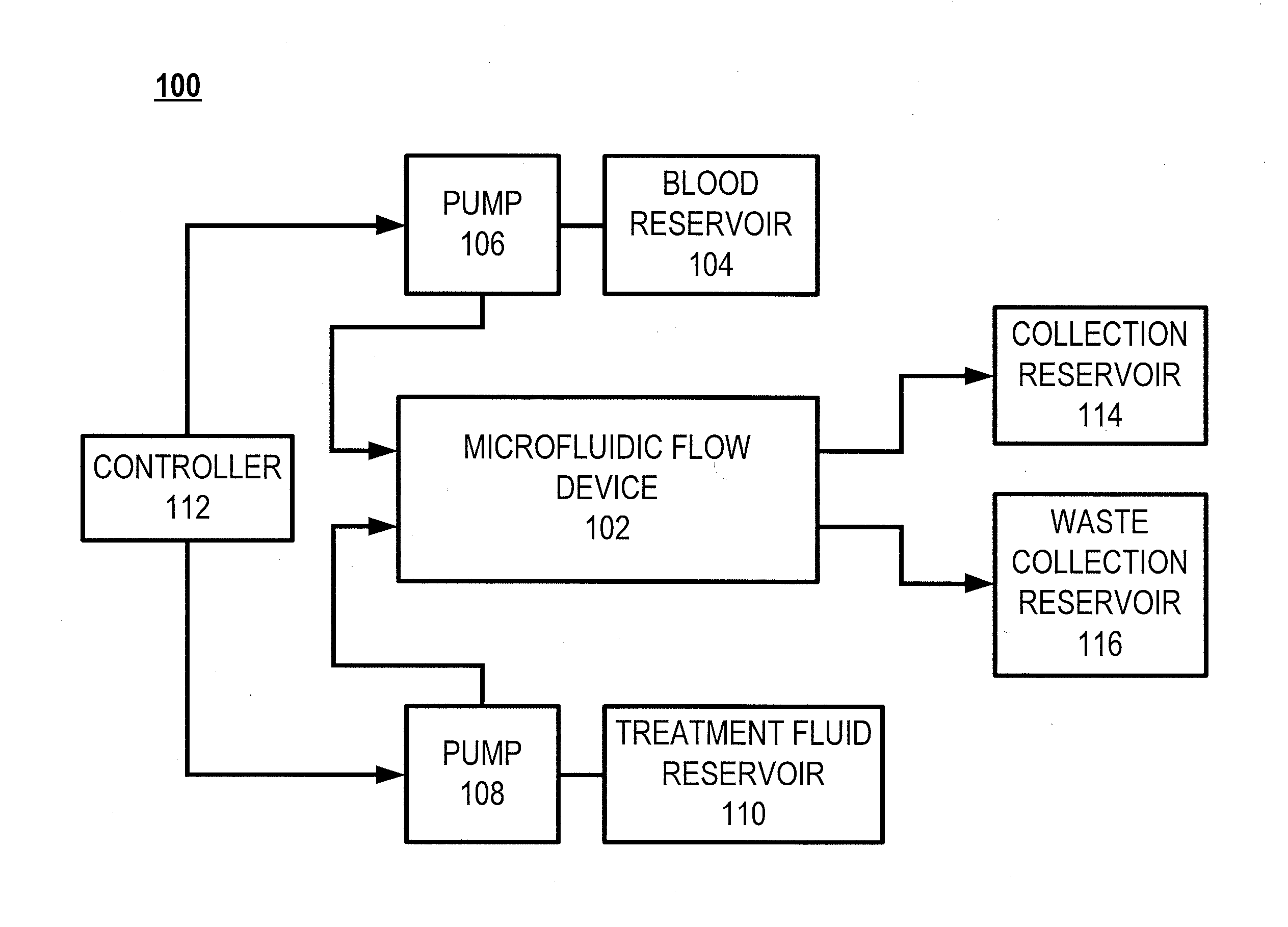
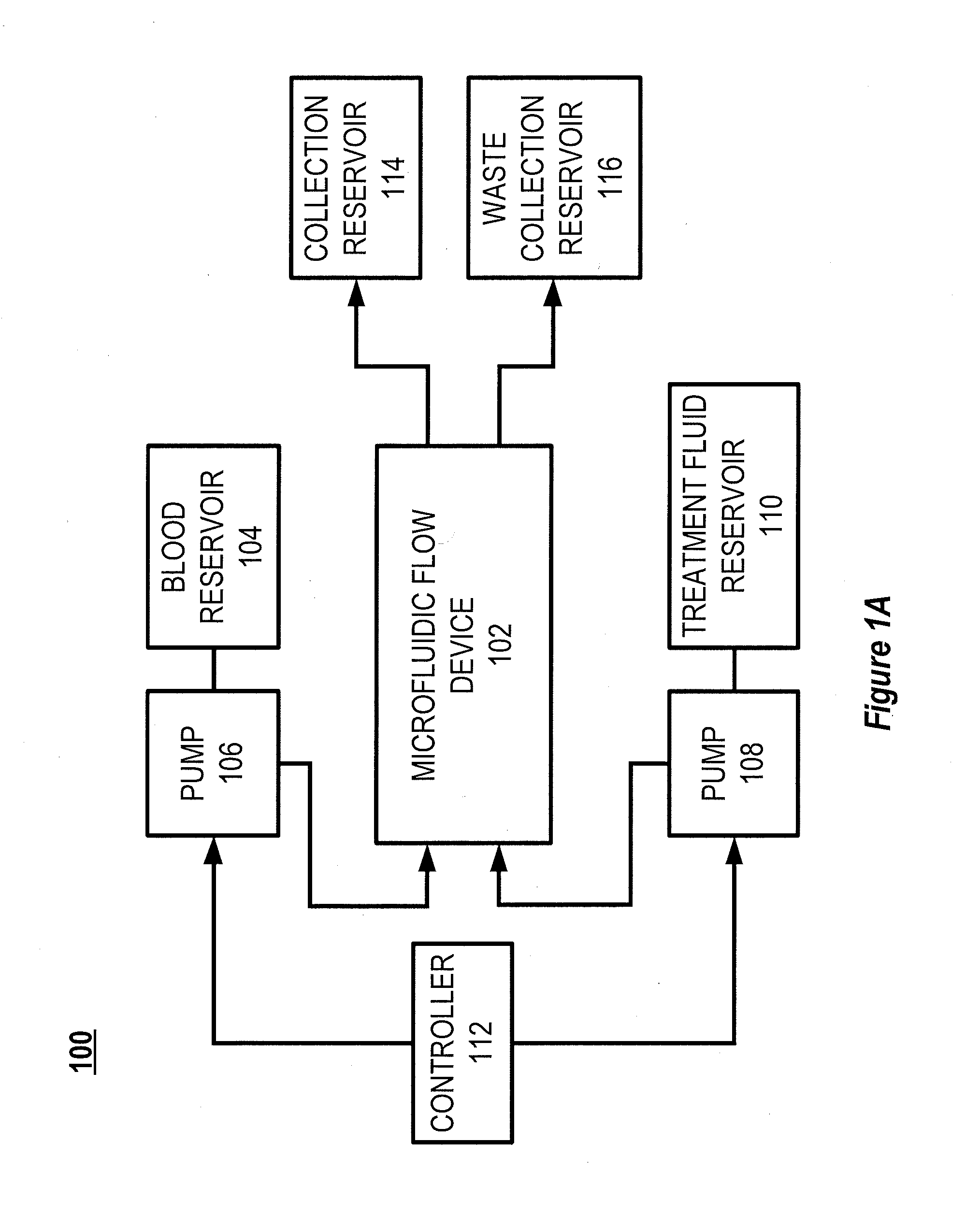
[0029]FIG. 1A illustrates a block diagram of an example system 100 for use with a microfluidic flow device 102. Blood from a blood reservoir 104 is pumped through one or more blood flow channels of the microfluidic flow device 102 by a first pump 106. A second pump 108 pumps treatment fluid (e.g., oxygen, dialysate, or infusate) from a treatment fluid reservoir 110 through one or more treatment fluid channels of the microfluidic flow device 102. The first pump 106 and the second pump 108 are controlled by a controller 112. Blood exiting the microfluidic flow device 102 is collected in a collection reservoir 114 and spent treatment fluid or other waste exiting the microfluid...


PUM

PropertyMeasurementUnit
Lengthaaaaaaaaaa
Lengthaaaaaaaaaa
Lengthaaaaaaaaaa

Abstract

The general disclosure discusses a system and method for improving the efficacy of blood filtration treatments such as hemodialysis, hemofiltration, and hemodiafiltration. More particularly, the disclosure discusses a microfluidic device that includes first and second channels separated by a permeable membrane. One of the channels is configured for blood flow and includes a protein gel disruption layer. The protein gel disruption layer includes a plurality of elements at least partially extending across the blood flow channel that reduce the formation of a boundary layer or gel layer at the blood-membrane interface.

Description

CROSS-REFERENCE TO RELATED PATENT APPLICATIONS[0001]This application claims priority to U.S. Provisional Patent Application 61 / 878,394, filed on Sep. 16, 2013 and titled “SYSTEM AND METHOD FOR DISRUPTING BOUNDARY LAYERS IN MICROFLUIDIC DEVICES,” which is incorporated herein by reference in its entirety.BACKGROUND OF THE DISCLOSURE[0002]Previous methods of achieving higher dialysis efficiencies, such as extending treatment time or flow rates, are inconvenient and expensive and can result in additional complications and problems with patient safety and quality of life. These methods can also result in undesirable effects on the blood.SUMMARY OF THE DISCLOSURE[0003]According to one aspect of the disclosure, a microfluidic device includes a first layer defining a first channel therein. The microfluidic device also includes a second layer defining a second channel therein. The second channel overlaps the first channel along a substantial portion of the length of the first channel. A memb...

Claims


Application Information

Patent Timeline
IPC IPC(8): A61M1/16
CPCA61M1/1621B01D61/28B01D63/088B01D63/085B01D2313/14B01D2325/08B01D65/08B01D2321/2016A61M2205/0244
Inventor BORENSTEIN, JEFFREY T.CHAREST, JOSEPH L.DIBIASIO, CHRISFINLEY, VIOLET
Owner JOHNSON & JOHNSON INNOVATION
Why Eureka
Try Eureka