

Multi-mode current-allocating device
- Summary
- Abstract
- Description
- Claims
- Application Information
AI Technical Summary
Benefits of technology
Problems solved by technology
Method used
Image

Examples
Embodiment Construction
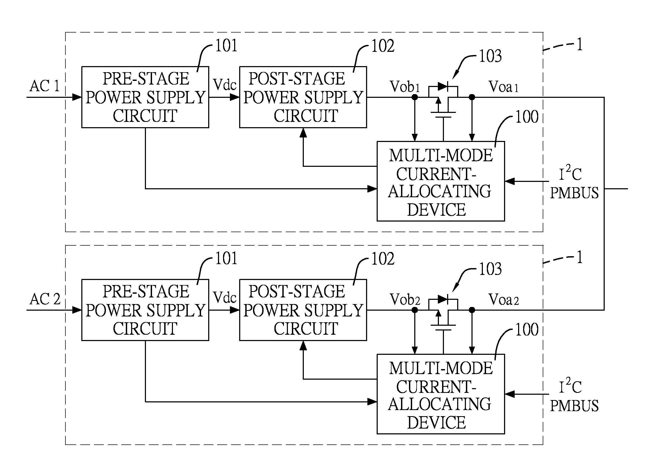
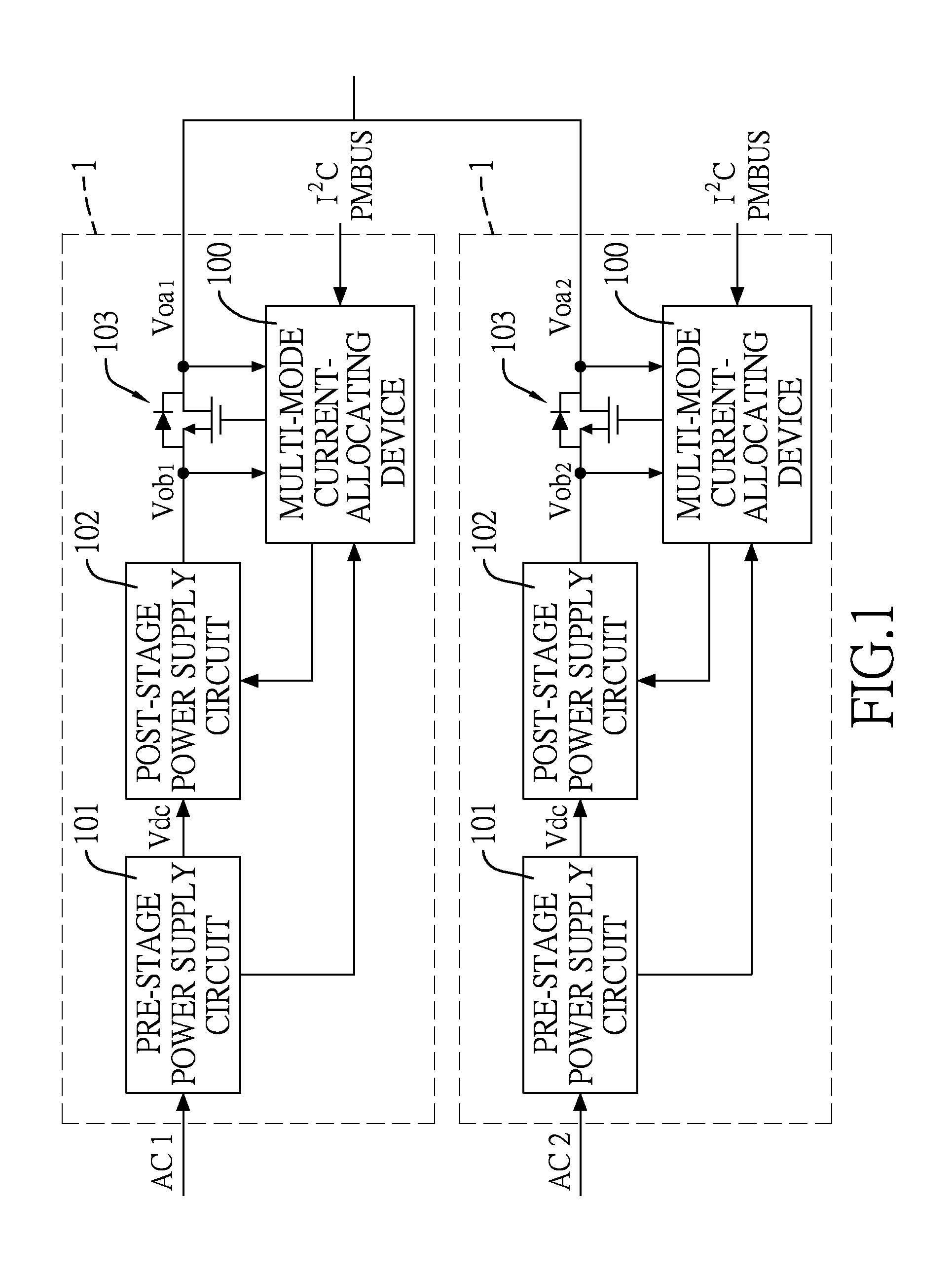
[0038]With reference to FIG. 1, multiple power supply devices 1 are connected in parallel to form a redundant power supply system. Each power supply device 1 at least has a DC to DC converter. In the present embodiment, each power supply device 1 has a pre-stage power supply circuit 101 and a post-stage power supply circuit 102. The pre-stage power supply circuit 101 converts an input voltage AC1, AC2 into a DC bus bar voltage Vdc, and may usually be a DC to DC converter with a PFC function. The post-stage power supply circuit 102 converts the DC bus bar voltage Vdc into an output voltage, and may usually be a DC to DC converter.
[0039]A multi-mode current-allocating device 100 is mounted inside each power supply device 1 to control the post-stage power supply circuit 102 inside the power supply device 1. An output terminal of the post-stage power supply circuit 102 is connected to a power bus of the power supply system through an Oring switch 103. The Oring switch 103 may be an Orin...
PUM
 Abstract
Description
Claims
Application Information