Method and system for an intake humidity sensor

a humidity sensor and humidity sensor technology, applied in the direction of machines/engines, combustion air/fuel air treatment, output power, etc., can solve the problems of overestimation of ambient humidity by the humidity sensor, affecting the adjustment of various engine operating parameters, and affecting the output of humidity sensors. , to achieve the effect of accurate ambient humidity estimate, accurate humidity overestimation due to egr flow, and increased backflow

Active Publication Date: 2015-03-26
FORD GLOBAL TECH LLC
View PDF0 Cites 11 Cited by
  • Summary
  • Abstract
  • Description
  • Claims
  • Application Information

AI Technical Summary

Benefits of technology

[0004]However, the inventors herein have identified potential issues with such an approach. As an example, during boosted engine operation, any opening of a compressor bypass valve (such as to mitigate or reduce compressor surge) can confound the humidity sensor output. Specifically, opening of the compressor bypass valve may create a (temporary) backflow of air from the charge air cooler outlet location to the compressor inlet location. The back-flowing air may temporarily raise the compressor inlet pressure for a short duration until the boost pressure is sufficiently reduced. The short duration of the increase in pressure at the compressor inlet can cause the air to flow back through an intake air filter to the atmosphere. The intake humidity sensor located between the air filter and the compressor inlet (or at the air filter) will see this back-flowing air. If low pressure EGR was already flowing when the compressor bypass valve was opened, the back-flowing air may have a higher water content (over and above the ambient humidity) due to the presence of EGR. As a result, ambient humidity may be over-estimated by the humidity sensor. As such, this may corrupt the adjustment of the various engine operating parameters while degrading engine performance.
[0007]In this way, a false reading of the humidity sensor is avoided. Specifically, the output of a humidity sensor may not be used during conditions when the output may be corrupted. By disabling use of a current output of the intake humidity sensor during conditions when a compressor bypass valve is open and backflow is increased, humidity overestimation due to EGR flow can be reduced. By freezing the humidity sensor output from before (e.g., immediately before) the compressor bypass event, and using the frozen sensor output to adjust engine operation, a more accurate ambient humidity estimate can be used to for engine adjustments. By unfreezing the humidity sensor output after (e.g., immediately after) a threshold duration since the compressor bypass event has elapsed, engine functions that depend on humidity information are not affected.

Problems solved by technology

However, the inventors herein have identified potential issues with such an approach.
As an example, during boosted engine operation, any opening of a compressor bypass valve (such as to mitigate or reduce compressor surge) can confound the humidity sensor output.
As a result, ambient humidity may be over-estimated by the humidity sensor.
As such, this may corrupt the adjustment of the various engine operating parameters while degrading engine performance.
Then, during boosted conditions where the compressor bypass valve is opened, such as when the engine is operating at or beyond a surge margin, the current output of the humidity sensor may not be used.
Specifically, the output of a humidity sensor may not be used during conditions when the output may be corrupted.

Method used


Image

  • Method and system for an intake humidity sensor
  • Method and system for an intake humidity sensor
  • Method and system for an intake humidity sensor

Examples


Embodiment Construction

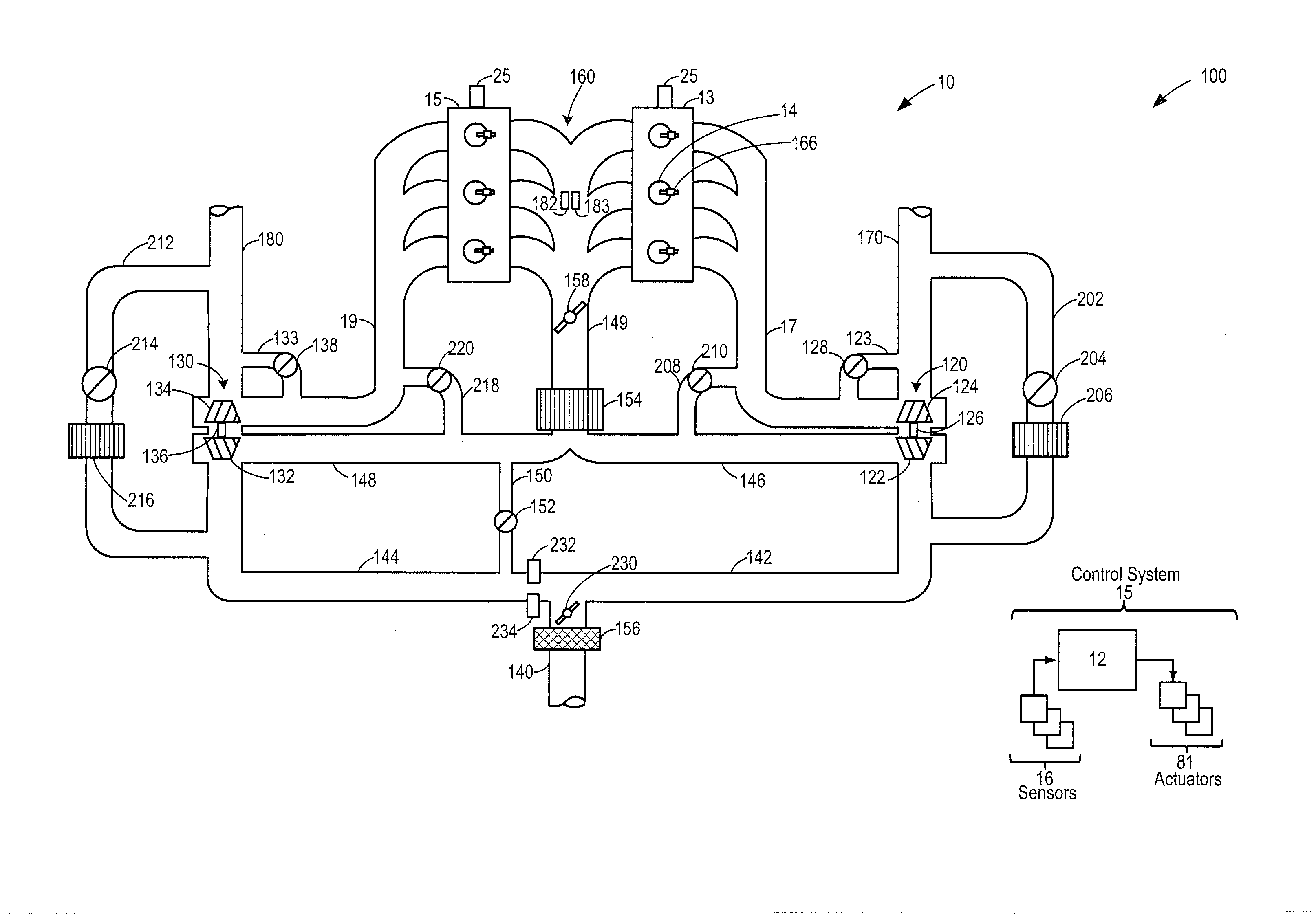
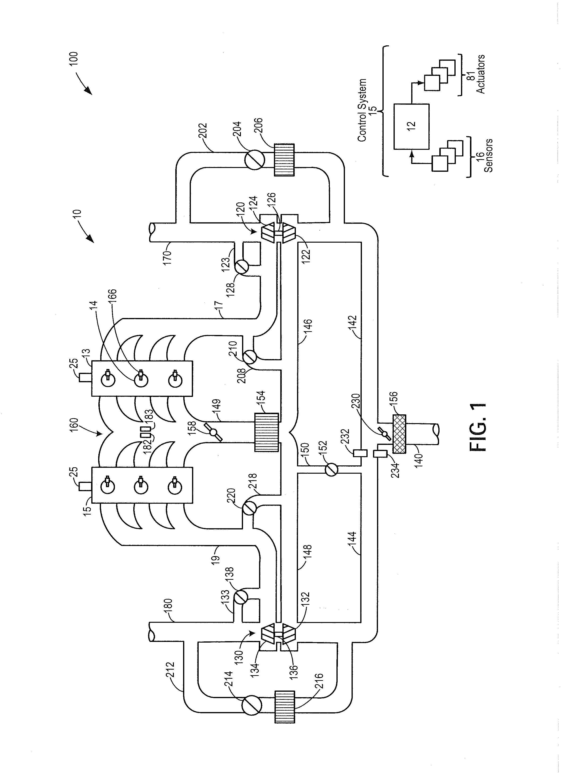
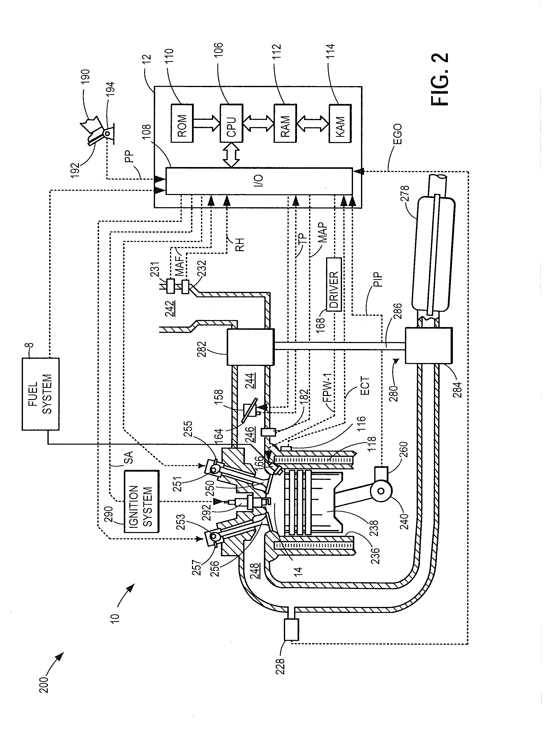
[0013]The following description relates to systems and methods for using the output of a humidity sensor coupled in an engine system (such as shown in FIGS. 1-2) to adjust on or more engine operating parameters. Based on whether a compressor bypass valve is open or closed, a current or stored output of the sensor is selected for estimating an ambient humidity. An engine controller may be configured to perform a control routine, such as the example routine of FIG. 3, to use the current output of the humidity sensor during conditions when a compressor bypass valve is closed to estimate an ambient humidity. Engine operating parameters may then be adjusted based on the current output based ambient humidity estimate. During conditions when the compressor bypass valve is open, such as when the engine is operating at or near surge, the current output of the humidity may not be used. Instead, an output of the humidity sensor read immediately before the bypass valve is opened may be stored a...


PUM


Abstract

Methods and systems are provided for adjusting an engine operating parameter based on an output of a humidity sensor during a compressor bypass valve event. When the compressor bypass valve is closed, a current output of the sensor is used for the adjustments. When the compressor bypass valve is opened, such as to mitigate surge, an output of the sensor stored from before the opening of the bypass valve is used for the adjustments.

Description

FIELD[0001]The present application relates to control of a humidity sensor in a boosted vehicle engine system during compressor bypass valve events.BACKGROUND AND SUMMARY[0002]Engine systems may be configured with exhaust gas recirculation (EGR) systems via which at least a portion of the exhaust gas is recirculated to the engine intake. Various sensors may be coupled in the engine system to estimate the amount of EGR being delivered to the engine. These may include, for example, various temperature, pressure, oxygen, and humidity sensors coupled to the engine intake manifold and / or the exhaust manifold.[0003]One example of a boosted engine system having an intake humidity sensor is shown by Surnilla et al. in US application 2012 / 0227714. Therein, the humidity sensor is used to infer an ambient humidity. An engine controller may then adjust one or more engine operating parameters, such as fuel injection, valve timing, EGR, etc., based on the estimated ambient humidity.[0004]However,...

Claims


Application Information

Patent Timeline
Patent Type & Authority Applications(United States)
IPC IPC(8): F02M25/07
CPCF02M25/0704F02M2025/0769F02M25/0753F02D13/02F02D23/00F02M35/10373F02M26/08F02M26/45F02M2026/009Y02T10/12
Inventor SURNILLA, GOPICHANDRACLARK, TIMOTHY JOSEPHSKOURES, EVANGELOSSOLTIS, RICHARD E.
Owner FORD GLOBAL TECH LLC
Why Eureka
Try Eureka