Purging device for pipe welding

a technology of purging device and pipe, which is applied in the direction of auxillary welding device, soldering apparatus, manufacturing tools, etc., can solve the problems of increasing the amount and injection time of ar gas to be injected into the pipe, secondary accidents, and increasing the effort required to form and remove the blocking layer, so as to prevent damage

Inactive Publication Date: 2015-03-26
PARK JIN WOO
View PDF1 Cites 24 Cited by
  • Summary
  • Abstract
  • Description
  • Claims
  • Application Information

AI Technical Summary

Benefits of technology

[0017]As described above, in a purging device for pipe welding according to an exemplary embodiment of the present invention, a pair of sealing tools and a gas controlling portion are protected and can be prevented from being damaged by heat generated during pipe welding, and flame retardant blocking layers are detachably coupled to the sealing tools so that a flame retardant blocking layer damaged during usage can be easily replaced with another one, and the gas controlling portion is formed of asbestos having a nonflammable property, or a cover formed of asbestos is detachably coupled to a pipe body that constitutes the gas controlling portion so that maintenance can be facilitated.

Problems solved by technology

In particular, when a length of the pipe is large, more effort is required to form and remove the blocking layer, and the injection quantity and injection time of the Ar gas to be injected into the pipe are increased.
Also, when the worker enters the inside of the pipe and checks the welded portions, there is a possibility that a secondary accident will occur due to the Ar gas that remains in the pipe, and in particular, a low oxygen concentration may be fatal to the worker.
However, in the conventional art, left and right air bags disposed inside the pipe may be damaged by heat generated during welding.
That is, the left and right air bags that are inserted into the pipe and then expanded using air supplied via an air supplying and exhausting portion may be damaged by heat generated during welding.

Method used


Image

  • Purging device for pipe welding
  • Purging device for pipe welding
  • Purging device for pipe welding

Examples


Embodiment Construction

[0022]Hereinafter, a purging device for pipe welding according to exemplary embodiments of the present invention will be described in detail with reference to the accompanying drawings. In the description of the present invention, if it is determined that a detailed description of well-known configuration or functions related to the invention is obvious to one of ordinary skill in the art, the detailed description will be omitted.

[0023]Also, same elements used in different positions in the following description are represented by the same reference numerals.

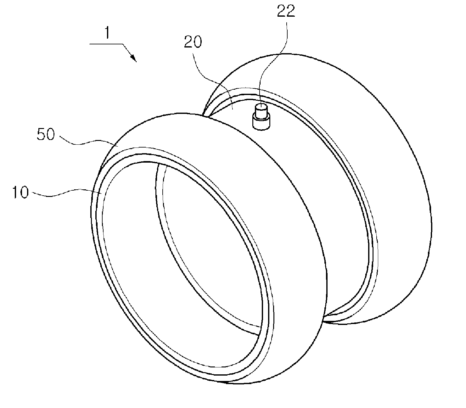
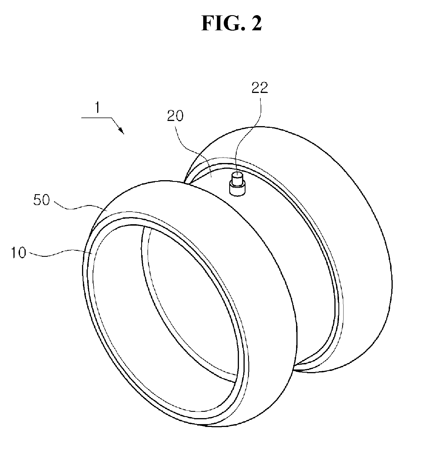
[0024]As illustrated in FIGS. 2 through 4, a purging device 1 for pipe welding according to an exemplary embodiment of the present invention includes a sealing tool 10, a connection pipe 20, and an air controlling portion 30. The sealing tool 10 further includes a flame retardant blocking layer 50.

[0025]The sealing tool 10 is inserted into right and left sides of a portion inside a pipe P to be welded expands using air supplied v...


PUM

PropertyMeasurementUnit
elasticityaaaaaaaaaa
LOIaaaaaaaaaa
lengthaaaaaaaaaa

Abstract

Disclosed is a purging device for pipe welding, comprising: a pair of sealing tools that are disposed inside a pipe, expand by supplied air and are in contact with an inner wall of the pipe; and a connection pipe that is disposed between the pair of sealing tools, is a cylindrical body, wherein the sealing tools are respectively fixed to either side end of the connection pipe and the connection pipe is provided with a gas nozzle for discharging inert gas supplied from the outside, wherein each of the sealing tools further comprises a blocking layer that is flame retardant and is coupled in such a manner as to surround an outer circumferential surface of each of the sealing tools.

Description

TECHNICAL FIELD[0001]The present invention relates to a purging device for pipe welding, and more particularly, to a purging device for pipe welding which is capable of preventing a purging device disposed inside a pipe from being damaged by heat generated during welding.BACKGROUND ART[0002]A purging operation is an operation in which a blocking layer is formed at one end of each of the pipes to be welded so as to prevent oxidation of welding beads and to obtain quality of welding when the pipes are welded and joined together and the pipes to be welded are fixed to face one another so that portions to be welded are in contact with one another and then the portions to be welded are taped and sealed and then an inert gas, such as argon (Ar), is injected into the pipe so as to prevent oxidation of the welding beads.[0003]After the purging operation is performed, the blocking layer is removed, and the Ar gas injected into the pipe is removed, and a worker enters an inside of the pipe an...

Claims


Application Information

Patent Timeline
Patent Type & Authority Applications(United States)
IPC IPC(8): B23K37/00B23K9/16
CPCB23K37/00B23K2201/10B23K9/16B23K9/326B23K37/0531B23K2101/10
Inventor PARK, JIN WOO
Owner PARK JIN WOO
Why Eureka
Try Eureka