
Method for welding two edges of one or more steel parts to each other including a heat treatment step after the welding step: penstock obtained with such a method

a technology of welding and penstock, which is applied in the direction of welding media, furnace types, non-disconnectible pipe joints, etc., can solve the problems of degrading mechanical properties in this zone of parts of the penstock, and the drawback of welding methods

Inactive Publication Date: 2015-03-26
ALSTOM RENEWABLE TECH
View PDF3 Cites 12 Cited by
  • Summary
  • Abstract
  • Description
  • Claims
  • Application Information

AI Technical Summary

Benefits of technology

The invention proposes a welding method that does not present the drawbacks of previous methods. The method includes a heat treatment after welding, where the weld bead and the HAZ are heated and then held at a specific temperature for a short time before being cooled. By controlling the heat treatment, the method can improve the quality of welds and the strength of the steel material. The heat treatment can be performed on specific zones of material and the whole weld bead and HAZ can be simultaneously heated and cooled. The method can be used on steel parts with high yield and tensile strengths and can also be performed using induction heating. The invention also relates to a penstock that is welded together by the proposed welding method.

Problems solved by technology

However, such welding methods present a drawback.
This results in particular in degraded mechanical properties in this zone of the parts of the penstock.

Method used


Image

  • Method for welding two edges of one or more steel parts to each  other including a heat treatment step after the welding step: penstock obtained with such a method
  • Method for welding two edges of one or more steel parts to each  other including a heat treatment step after the welding step: penstock obtained with such a method
  • Method for welding two edges of one or more steel parts to each  other including a heat treatment step after the welding step: penstock obtained with such a method

Examples


Embodiment Construction

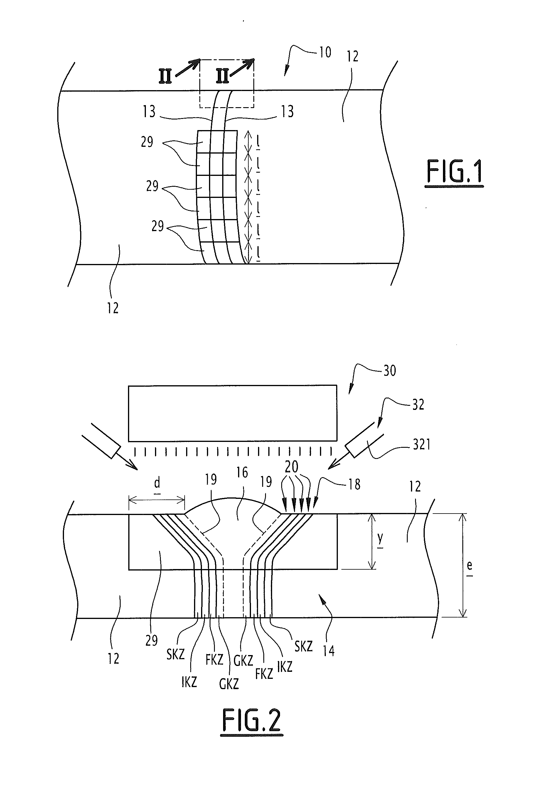
[0039]Referring to FIG. 1, a penstock 10 according to the invention is intended to be used to convey a pressurized liquid, for example water, and comprises a plurality of parts 12 made of thermomechanical HLE steel.

[0040]As indicated previously, the thermomechanical HLE steels exhibit mechanical properties close to the so-called quenched-tempered steels, hereinafter called “QT steels”, but with a substantially lower carbon content.

[0041]This is reflected in a good matching of these thermomechanical HLE steels to the welding.

[0042]The creation of thermomechanical HLE steels is differentiated from that of QT steels in that it comprises the performance of a hot rolling operation followed by a rolling operation at a temperature that is both lower than the recrystallization temperature of the austenitic grains and higher than the solid state phase transformation start temperature. This second rolling operation is itself followed by a cooling operation that is accelerated and controlled i...


PUM

PropertyMeasurementUnit
thicknessaaaaaaaaaa
thicknessaaaaaaaaaa
thicknessaaaaaaaaaa

Abstract

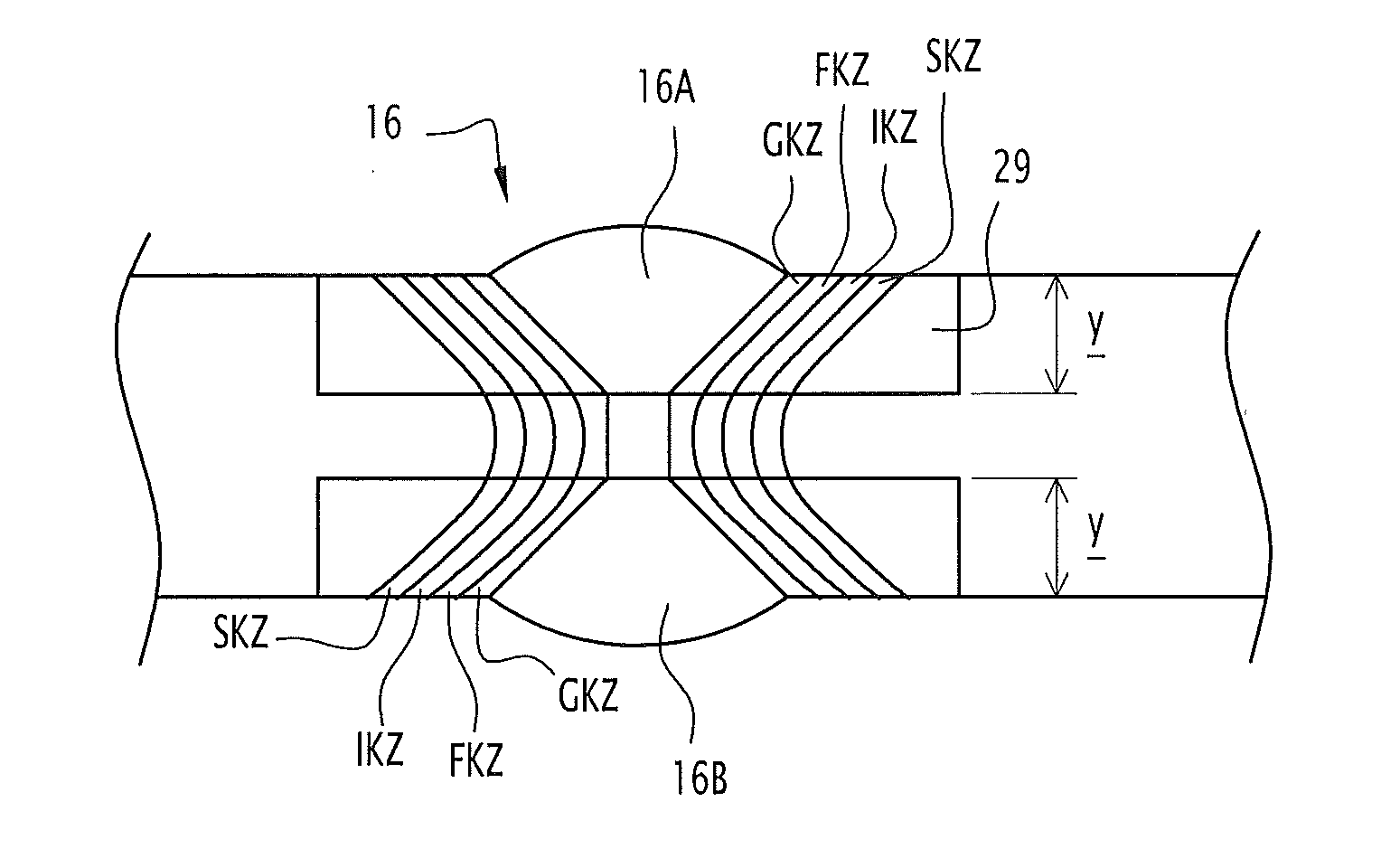
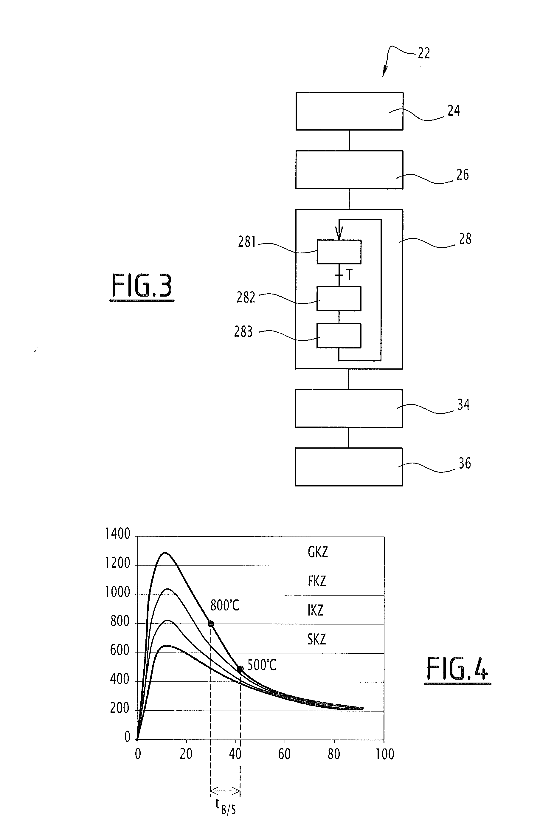
The present application describes a method for welding two parts to each other. The two parts are made from steel having a high thermomechanical yield strength. The welding method includes a welding step in which a weld bead is created inducing a heat-affected zone to appear. The method also includes a heat treatment step having a heating step, during which at least one portion of the weld bead and the HAZ is gradually heated to a treatment temperature; then a holding step in which the portion of the weld bead and the HAZ is kept at the treatment temperature; then a cooling step in which the HAZ and the weld bead are gradually cooled and pass from the austenitic transformation end temperature to the martensitic transformation end temperature of the steel of the parts in a time between 7.5 s and 8.5 s, and pass from the austenitic transformation end temperature to the martensitic transformation end temperature in a time shorter than 15.5 s. The present application also describes a penstock obtained with such a method.

Description

CROSS-REFERENCE TO RELATED APPLICATIONS[0001]This application claims priority to PCT / EP2013 / 061535 filed Jun. 5, 2013, which claims priority to French application 1255239 filed Jun. 5, 2012, both of which are hereby incorporated in their entireties.TECHNICAL FIELD[0002]The present invention relates to a method for welding together two edges of one or more parts produced from steel.[0003]More particularly, the invention relates to a method for welding two edges of one or more parts together, the or each part being produced from thermomechanical high yield strength (HLE) steel whose composition simultaneously meets the following conditions:[0004]0.02%≦C≦0.12%, C being of the mass carbon content of the steel, expressed as a percentage by weight, and[0005]0.20%≦C+(Mn+Mo) / 10+(Cr+Cu) / 20+Ni / 40≦0.505%, with C, Mn, Mo, Cr, Cu and Ni being respectively the mass carbon, manganese, molybdenum, chromium, copper and nickel contents of the steel expressed as a percentage by weight, said welding me...

Claims


Application Information

Patent Timeline
Patent Type & Authority Applications(United States)
IPC IPC(8): C21D9/50F16L13/02B23K31/02
CPCC21D9/505C21D2211/001F16L13/02B23K31/02B23K9/02B23K9/173B23K35/004B23K35/3073B23K2103/04C21D2211/002C21D2211/008
Inventor PRIGENT, SERGEDUPARCHY, FLORIANDONCOURT, ARNAUD
Owner ALSTOM RENEWABLE TECH
Learn More