Automatic traction relay valve diagnostic using pressure transducer feedback

Inactive Publication Date: 2015-03-26
BENDIX COMML VEHICLE SYST LLC
View PDF20 Cites 11 Cited by
  • Summary
  • Abstract
  • Description
  • Claims
  • Application Information

AI Technical Summary

Benefits of technology

[0006]The present disclosure sets forth a method of detecting a relay valve unintended pneumatic act

Problems solved by technology

Unintended relay valve pneumatic application due to leakage or other causes is undesirab

Method used


Image

  • Automatic traction relay valve diagnostic using pressure transducer feedback
  • Automatic traction relay valve diagnostic using pressure transducer feedback
  • Automatic traction relay valve diagnostic using pressure transducer feedback

Examples


Example

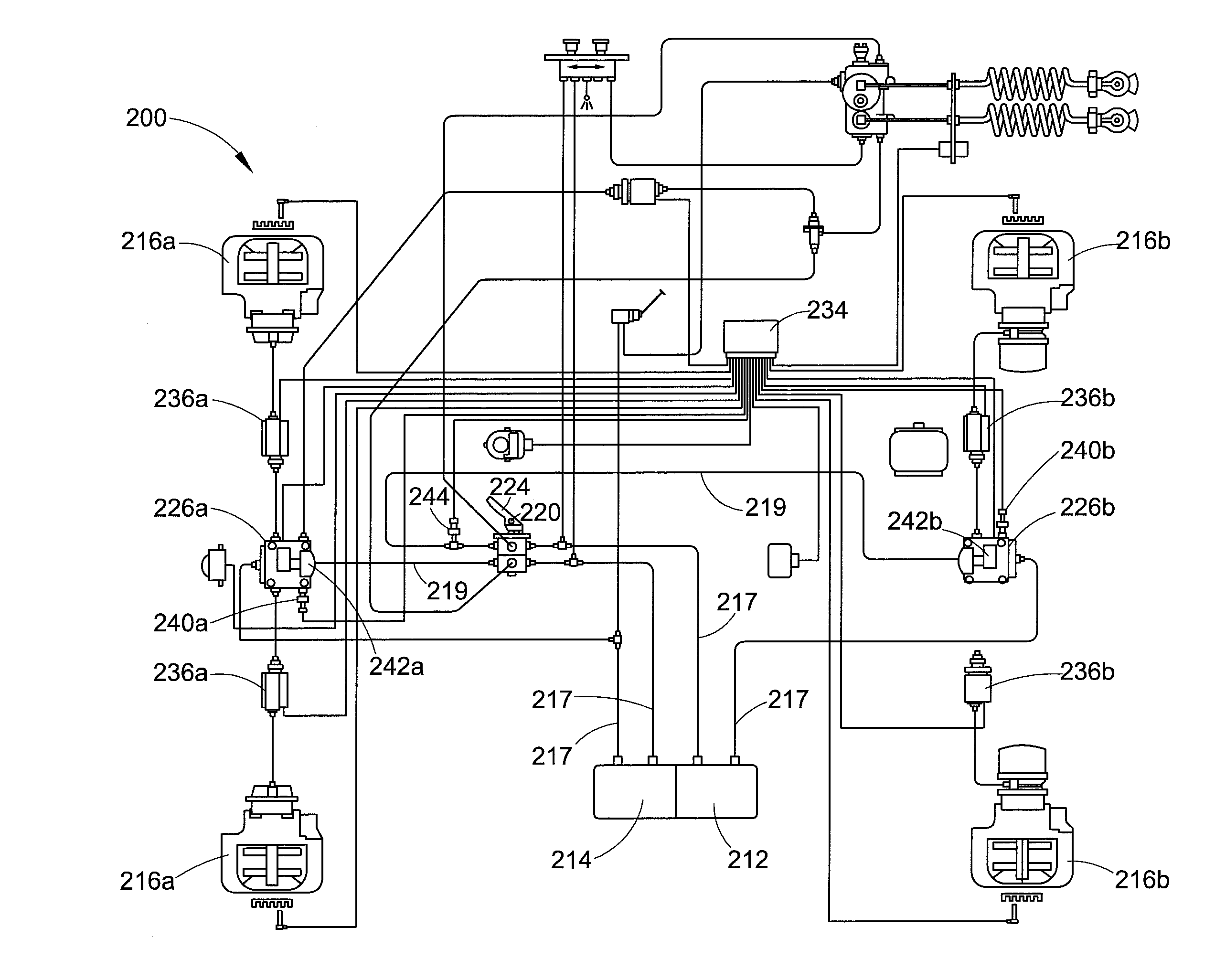
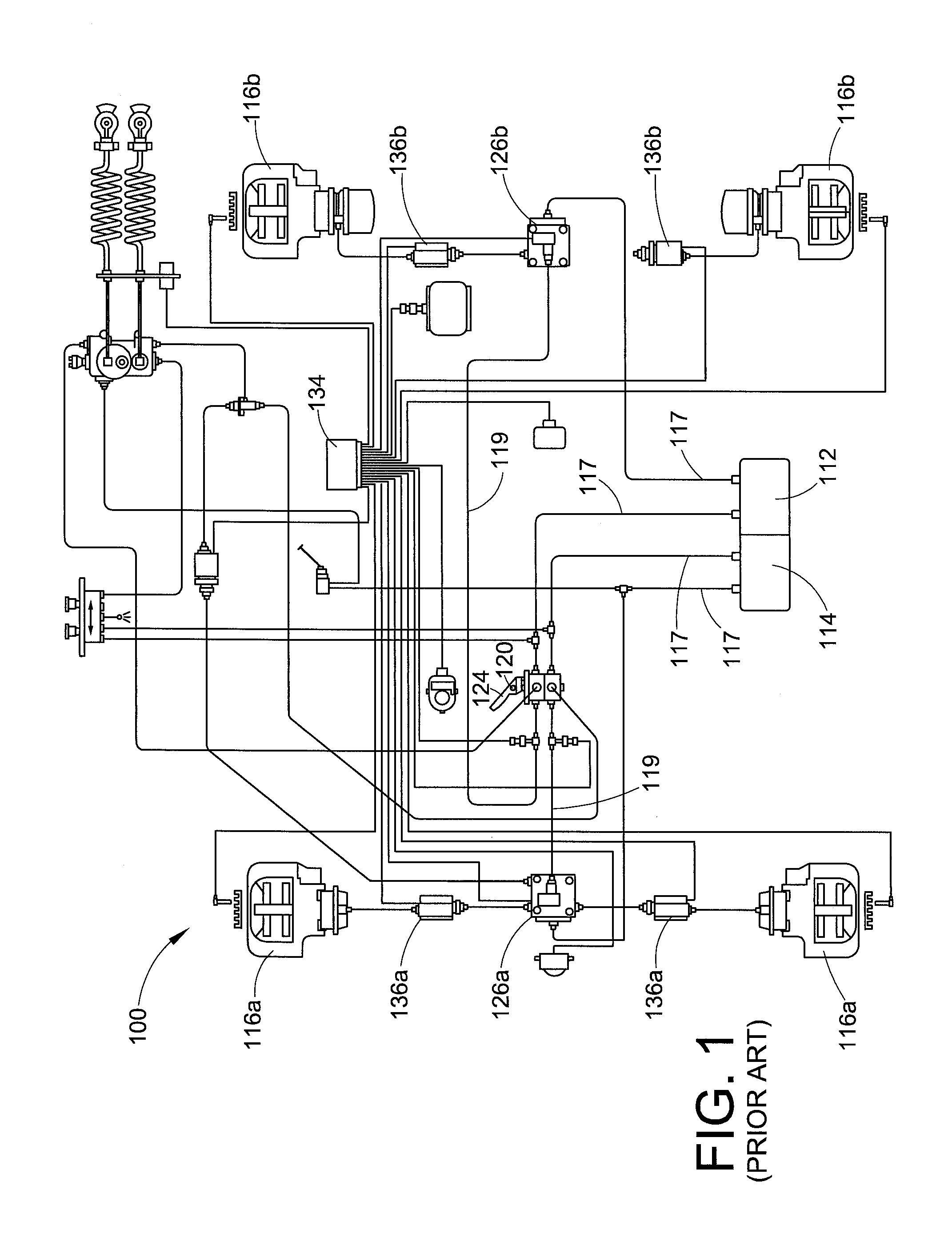
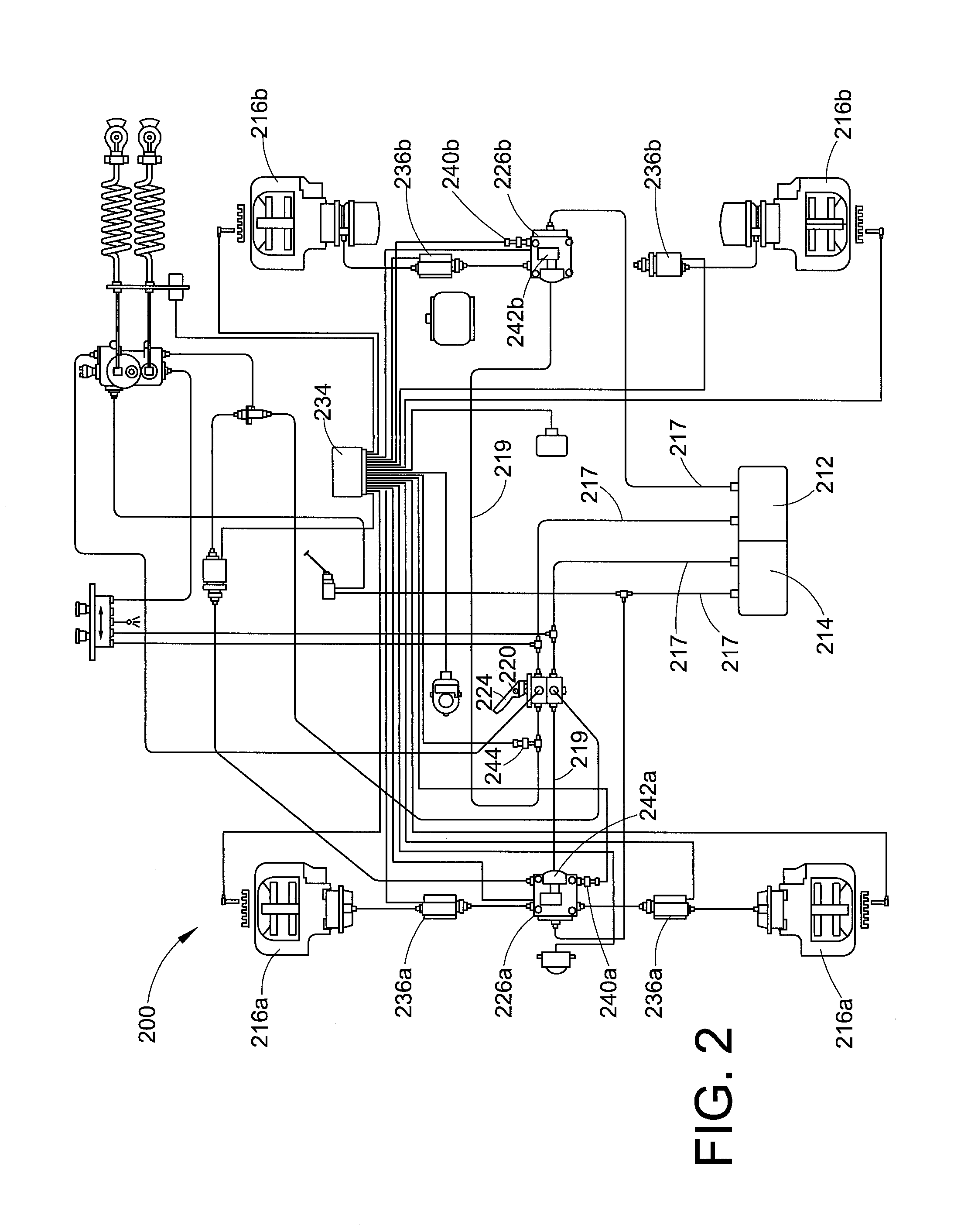
[0020]With reference to FIG. 1, an exemplary prior art air brake system is illustrated. The brake system 100 includes primary air reservoir 112 (typically for supplying a rear or trailer brake circuit) and secondary air reservoir 114 (typically for supplying a front or tractor brake circuit). The primary and secondary air reservoirs 112, 114 supply pressurized air to apply a set of front service brake assemblies 116a and rear service brake assemblies 116b. Air lines 117 communicate the pressurized air from the reservoirs 112, 114 to the brake assemblies 116a, 116b, via the various components of the system.

[0021]The air brake system 100 also includes a brake valve 120 having a foot pedal 124 that opens the valve when depressed. When open, the brake valve 120 allows pressurized air to flow from the reservoirs 112, 114 to relay valves 126a and 126b for actuating the service brakes.

[0022]Relay valves 126a and 126b also provide pressurized air to the brake assemblies 116a and 116b during...


PUM


Abstract

A system and method of diagnosing and/or mitigating the effects of a malfunctioning brake valve configured to supply pressurized fluid to a brake unit via a pressure delivery line during automated braking operations including detecting a period of no braking activity, venting the pressure delivery line to atmosphere during the period of no braking activity, monitoring pressure in the pressure delivery line to detect a pressure change resulting from the venting, and generating an error signal if a detected pressure change exceeds a threshold value. The pressure modulating valve can be periodically cycled once a fault is detected to reduce the effects thereof.

Description

BACKGROUND[0001]The present exemplary embodiment relates to a braking system for a vehicle. It finds particular application in conjunction with braking systems having automated braking functionality, and will be described with particular reference thereto. However, it is to be appreciated that the present exemplary embodiment is also amenable to other like applications.[0002]A typical vehicle braking system for a straight truck, bus, tractor, or trailer, includes a source of pressurized air along with valves for selectively directing the air to brake chambers at the wheels of the vehicle. Vehicle air brake systems typically include a primary circuit, which is often used for driven wheels, and a secondary circuit, which is often used for non-driven wheels. A foot brake valve (FBV) is provided for enabling a user to apply the brakes. The FBV is often a valve in both the primary circuit and the secondary circuit that is controlled by a foot pedal (brake pedal) of the vehicle in respons...

Claims


Application Information

Patent Timeline
IPC IPC(8): B60T17/22B60T11/10
CPCB60T11/103B60T17/221B60T8/4809B60T8/885
Inventor TOBER, MICHAEL D.CARRITTE, TIMOTHYFRASHURE, TIMOTHY J.
Owner BENDIX COMML VEHICLE SYST LLC
Why Eureka
Try Eureka