Dc/dc converter

a converter and converter technology, applied in the direction of electric variable regulation, process and machine control, instruments, etc., can solve the problems of greater power conversion efficiency decline, intermittent oscillation operation is disabled, and intermittent oscillation operation is performed

Active Publication Date: 2015-03-26
SANKEN ELECTRIC CO LTD
View PDF10 Cites 16 Cited by
  • Summary
  • Abstract
  • Description
  • Claims
  • Application Information

AI Technical Summary

Benefits of technology

[0024]A DC / DC converter according to a first aspect of the invention is a DC / DC converter configured to convert a first DC voltage into a second DC voltage by turning on and off a switching element in accordance with a drive signal generated by a control circuit, in which the control circuit includes: an oscillator configured to output pulses at a predetermined frequency; an error amplifier configured to amplify an error between the second DC voltage and a reference voltage and output an amplified error signal; an inductor connected to the switching element and an output terminal of the second DC voltage; a zero crossing detection circuit configured to output a zero crossing signal when a regeneration period of the inductor is completed; a light load detection circuit configured to compare the amplified error signal from the error amplifier and a threshold and output a light load signal; a timer circuit configured to output an intermittent operation enabling signal after an elapse of a predetermined period of time based on the light load signal from the light load detection circuit and the zero crossing signal from the zero crossing detection circuit, and output an intermittent operation disabling signal when a period without output of the zero crossing signal continues for a predetermined period of time; and an ON-OFF control controller configured to turn off the switching element when the amplified error signal falls below the threshold while the timer circuit is outputting the intermittent operation enabling signal, and turn on the switching element when the amplified error signal at least reaches or exceeds the threshold while the timer circuit is outputting the intermittent operation enabling signal.

Problems solved by technology

However, such a circuit continues its switching operation even in a light load state such as a standby state, and therefore the lighter the load, the greater the power conversion efficiency decreases.
As a result, an intermittent oscillation operation is disabled.
However, in the case of U.S. Pat. No. 5,481,178, there is a first problem as below.
This leads to a problem in that an intermittent oscillation operation is performed even in a heavy load range where a steady oscillation operation should be performed.
Moreover, there is a second problem as below.
In the real situation, however, there is a response delay in the amplified error signal COMP, and the amplified error signal COMP cannot quickly drop below the first light load detection threshold (Vsk_Lo).
Thus, the ripple voltage superimposed on Vout is increased, and the intermittent oscillation OFF period becomes unnecessarily long.
In a case of using a ceramic capacitor as the output capacitor 10, such frequency leads to a problem in that acoustic noises are generated due to its piezoelectric effect.
Moreover, there is a third problem in that there is no current difference between the load current at which the intermittent oscillation operation is started and the load current at which the intermittent oscillation operation is ended, and therefore the operation becomes unstable in a near-threshold load range.
According to Japanese Patent Application Publication No. 2007-020352, the second problem may be reduced, but the first and third problems are not yet to be solved.

Method used


Image

  • Dc/dc converter
  • Dc/dc converter
  • Dc/dc converter

Examples


embodiment 1

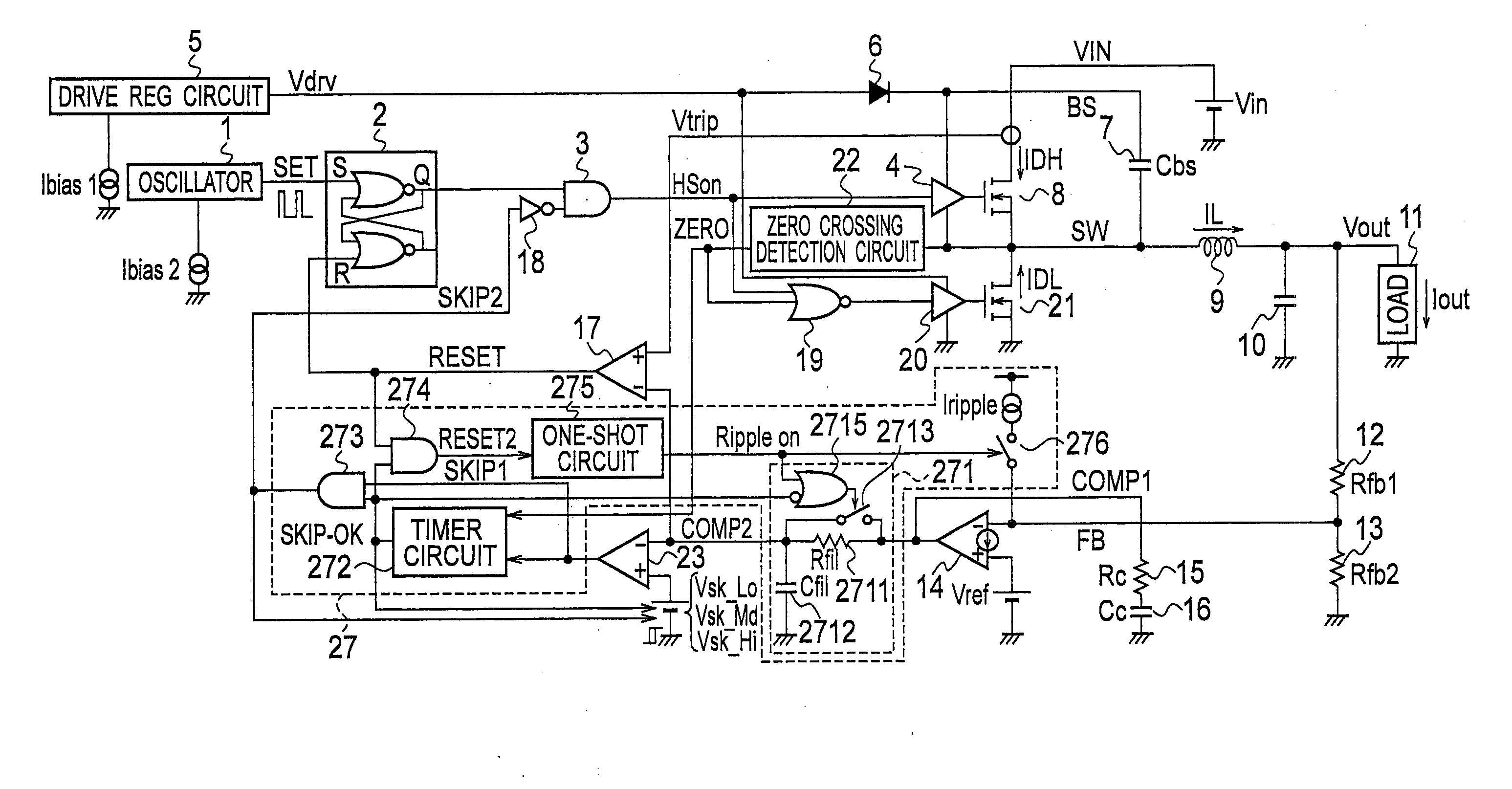
[0048]FIG. 4 is a circuit configuration diagram of a DC / DC converter of Embodiment 1 of the present invention. FIG. 5 is a specific circuit configuration diagram of a zero crossing detection circuit in the DC / DC converter of Embodiment 1 of the present invention. FIG. 6 is a specific circuit configuration diagram of a timer circuit in the DC / DC converter of Embodiment 1 of the present invention.

[0049]The DC / DC converter of Embodiment 1 is a DC / DC converter configured to convert a first DC voltage into a second DC voltage by turning on and off switching elements in accordance with drive signals generated by a control circuit.

[0050]An oscillator 1 is configured to output pulses at a predetermined frequency. An error amplifier 14 is configured to amplify the error between the second DC voltage and a reference voltage and output an amplified error signal. An inductor 9 is connected to MOSFETs 8, 21 formed of switching elements and the output terminal of a second DC voltage Vout. A zero ...

embodiment 2

[0094]FIG. 11 is a circuit configuration diagram of a DC / DC converter of Embodiment 2 of the present invention. FIG. 12 is a timing chart for describing the operations of parts in the DC / DC converter of Embodiment 2 of the present invention.

[0095]The DC / DC converter of Embodiment 2 illustrated in FIG. 11 is characterized in that an AND circuit 24, a switch 25, and a switch 26 are provided additionally to the DC / DC converter of Embodiment 1 illustrated in FIG. 4. Note that description of the same constituent components as those illustrated in FIG. 4 is omitted.

[0096]The switch 25 is connected to one end of a drive REG circuit 5 and one end of a bias source Ibias1. The switch 26 is connected to one end of an oscillator 1 and one end of a bias source Ibias2. The AND circuit 24 is configured to AND a zero crossing signal from a zero crossing detection circuit 22 and SKIP2 from an AND circuit 273 and output a signal BIAS_OFF to the switch 25 and the switch 26.

[0097]Next, operations will ...

embodiment 3

[0100]FIG. 13 is a circuit configuration diagram of a DC / DC converter of Embodiment 3 of the present invention. FIG. 14 is a timing chart for describing the operations of parts in the DC / DC converter of Embodiment 3 of the present invention.

[0101]The DC / DC converter of Embodiment 3 is characterized in that the intermittent oscillation operation control circuit 27 of the DC / DC converter of Embodiment 1 illustrated in FIG. 4 is changed to an intermittent oscillation operation control circuit 27b.

[0102]The intermittent oscillation operation control circuit 27b is obtained by removing the current source Iripple and the switch 276 from the intermittent oscillation operation control circuit 27 and adding a reference voltage Vref2 and a switch 277 thereto.

[0103]The common terminal of the switch 277 is connected to the non-inverting input terminal of an error amplifier 14, a reference voltage Vref1 is connected to the first switching terminal of the switch 277, and a reference voltage Vref...


PUM


Abstract

The present invention includes: a zero crossing detection circuit which outputs a zero crossing signal when an inductor's regeneration period is completed; a light load detection circuit which compares an amplified error signal from an error amplifier and a threshold and outputs a light load signal; a timer circuit which outputs an intermittent operation enabling signal after a predetermined period based on the light load signal and zero crossing signal and outputs an intermittent operation disabling signal when the zero crossing signal is not outputted for a predetermined period; and an ON-OFF control controller which turns off a switching element when the amplified error signal falls below the threshold while the timer circuit is outputting the intermittent operation enabling signal, and turns on the switching element when the amplified error signal at least reaches or exceeds the threshold while the timer circuit is outputting the intermittent operation enabling signal.

Description

TECHNICAL FIELD[0001]The present invention relates to a DC / DC converter.BACKGROUND ART[0002]As means for generating a stable voltage lower than an input voltage, non-insulated step-down chopper circuits have been widely used. However, such a circuit continues its switching operation even in a light load state such as a standby state, and therefore the lighter the load, the greater the power conversion efficiency decreases.[0003]To solve this problem, a method has been proposed in which an error signal generated by comparing an output voltage and a reference voltage is compared with a predetermined threshold to detect a light load and, once a light load state is reached, the ON and OFF of a switching transistor are controlled according to the pulsation of the error signal to repeat intermittent operations.[0004]In this control method, the lighter the load, the lower the frequency of the switching operation becomes. This enables reduction in the switching loss, and also reduction in t...

Claims


Application Information

Patent Timeline
Patent Type & Authority Applications(United States)
IPC IPC(8): H02M1/08H02M3/158H02M1/00
CPCH02M1/08H02M2001/0032H02M3/158H02M3/156H02M1/0032H02M1/0035Y02B70/10
Inventor NAKAMURA, MASARUNAKAMURA, HIROAKIKONISHI, TAKAYUKIISSHI, CHIENAKAMOTO, SATOSHI
Owner SANKEN ELECTRIC CO LTD
Why Eureka
Try Eureka