
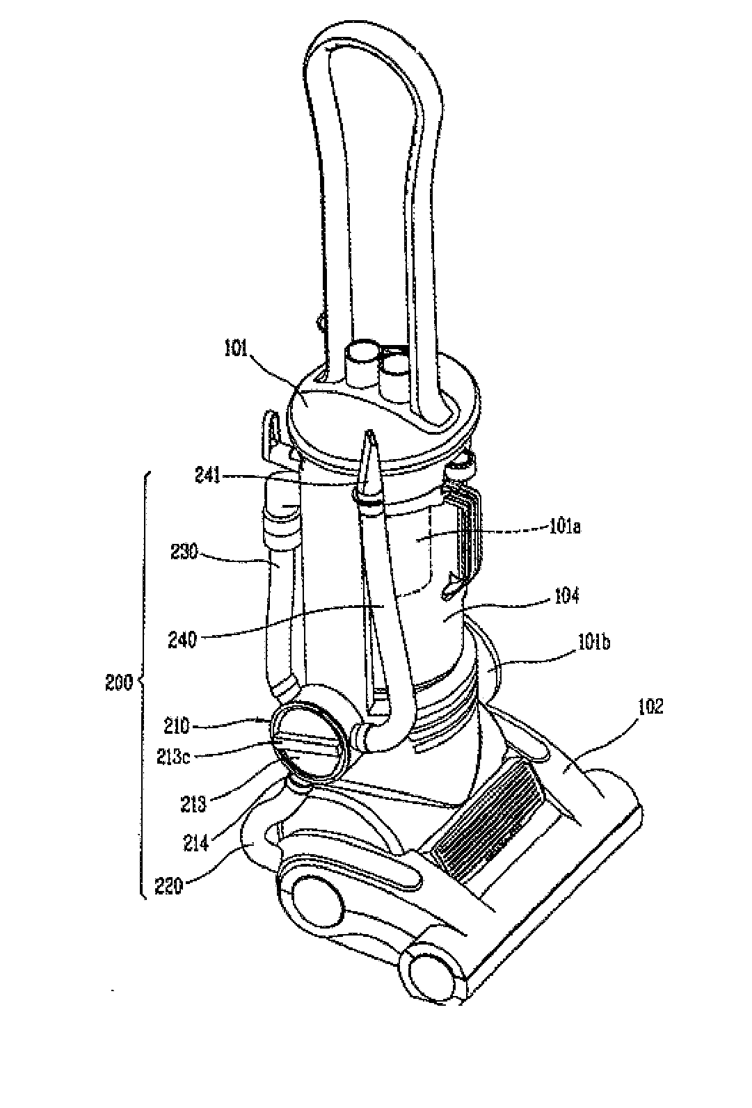
Vertical vacuum cleaner

a vacuum cleaner and vertical technology, applied in the field of vacuum cleaners, can solve the problems of insufficient dust absorption of conventional upright vacuum cleaners, inability to effectively play the other position's effective role, and insufficient use of upright vacuum cleaners with conversion valves in the prior ar

Active Publication Date: 2015-04-02
ECOVACS ROBOTICS (SUZHOU ) CO LTD
View PDF2 Cites 3 Cited by
  • Summary
  • Abstract
  • Description
  • Claims
  • Application Information

AI Technical Summary

Benefits of technology

The present invention provides an upright vacuum cleaner that can clean open ground and other positions such as hidden corners, steps, and table tops. It ensures smooth airflow, compact structure, easy packaging, and durability against breakage. The conversion valve of the cleaner is positioned on the back surface of the cleaner body and inward recess between the dust collection chamber and motor chamber, which reduces the exposed parts of the air inlet and outlet pipes and allows for a more compact pipeline system. The technical effects achieved through this design include improved air flow, energy efficiency, compact structure, space saving, easy packing, and indestructibility.

Problems solved by technology

In general, the conventional upright vacuum cleaner is suitable for cleaning the indoor open ground, but encounters difficulties in playing its effective role on the other positions such as hidden corners, steps and table tops.
Except for by the air inlet of the ground brush close to the ground, the conventional upright vacuum cleaner has no other means to absorb dust.
However, the upright vacuum cleaner with conversion valve in the prior art has deficiencies, in particular the unreasonable arrangement of pipes (air ducts).
Since the soft pipe or hard pipe is provided on the outside of ground brush, such arrangement is not compact in overall structure and thus occupies more space; Furthermore, since the air inlet pipe of the conversion valve is exposed outside as a whole, it may be easily damaged and does not facilitate product packaging; In particular, since the air inlet pipe of the conversion valve is exposed as a whole on the outside of ground brush, the pipe collecting pipe is relatively longer, thus the energy loss of air in the process of flowing in the pipe is increased, leading to inadequate smoothness of air flow.

Method used


Image

  • Vertical vacuum cleaner
  • Vertical vacuum cleaner
  • Vertical vacuum cleaner

Examples


Embodiment Construction

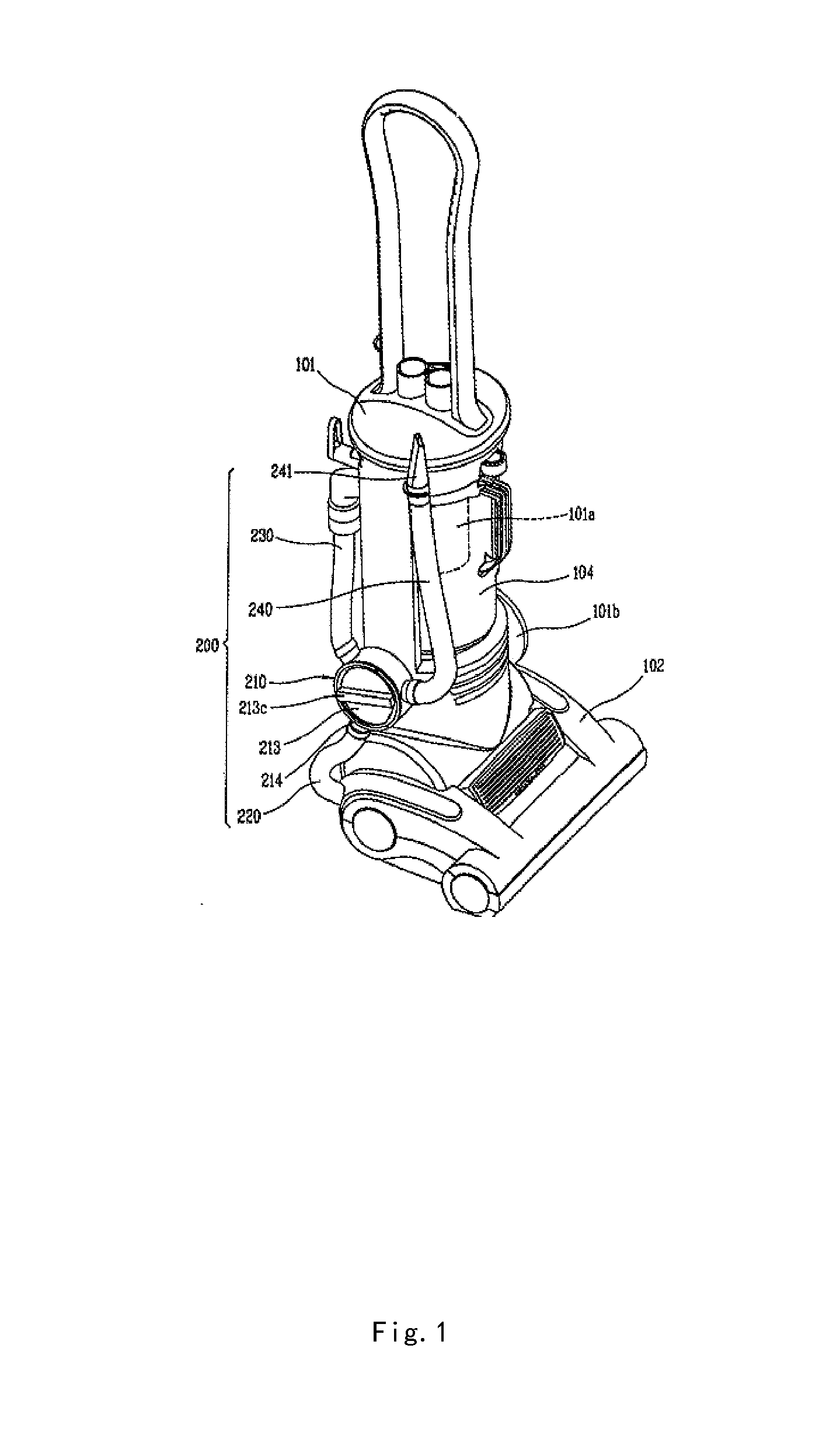
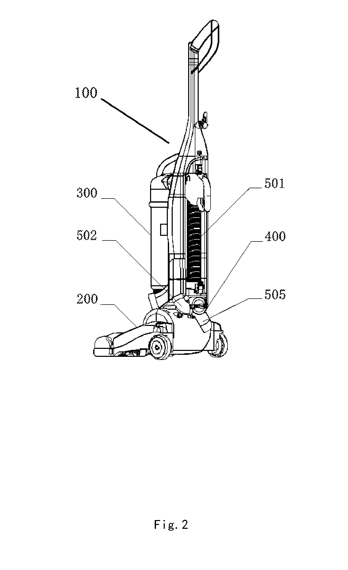
[0043]Referring to FIGS. 2-6, an upright vacuum cleaner is illustrated, which comprises the following devices and systems.

[0044]The upright vacuum cleaner comprises a cleaner body 100, a ground brush 200, a dust collection chamber 300, a conversion valve 400 and a pipeline system.

[0045]The ground brush 200 is positioned at the lower part of the cleaner body and is provided with an air inlet of the ground brush 201, a rolling brush 202 and a motor chamber.

[0046]The dust collection chamber 300 is positioned above the ground brush 200 and is provided with an air inlet 301 and an exhaust outlet 302.

[0047]The conversion valve 400 is provided in the back surface of the cleaner body 100 and is positioned at an inward recess between the ground brush 200 and the dust collection chamber 300, and the conversion valve 400 comprises a conversion valve body 401, a conversion valve casing 402 and a conversion valve knob 403. The conversion valve body 401 is disposed within the conversion valve cas...


PUM


Abstract

The present invention discloses an upright vacuum cleaner which comprises a cleaner body (100), a ground brush (200), a dust collection chamber (300), a conversion valve and a pipeline system. The conversion valve (400) is disposed at the outside of the back surface of the cleaner body (100) and is located at an inward recess between the dust collection chamber (300) and the ground brush (200). The conversion valve (400) is provided with a first air inlet, a second air inlet and an air outlet of the conversion valve. The pipeline system comprises a suction soft pipe (501), an air duct (203) of the floor brush, a machine body air inlet duct (503), a machine body air outlet duct (504) and a motor chamber exhaust pipe. The pipeline system further comprises a motor chamber air inlet pipe (505) of which one end is connected with the air duct (203) of the ground brush, and the other end is connected with the first air inlet (505) of the conversion valve after passing through the motor chamber and being bend upward against the outside of the back surface of the floor brush. The upright vacuum cleaner can clean not only the floor but also other places above the floor. The upright vacuum cleaner provides an unblocked air flow, has a compact structure, saves spaces, is convenient to package, and is not easily damaged.

Description

FIELD OF THE INVENTION[0001]The present invention relates to a vacuum cleaner, in particular an upright vacuum cleaner.BACKGROUND OF THE PRIOR ART[0002]The conventional upright vacuum cleaner comprises a cleaner body (also known as cleaner casing or upright body), a ground brush (also generally named as suction nozzle), a dust collection chamber and a pipeline system (also known as air duct system). The ground brush is positioned at the lower part of the cleaner body and is provided with an air inlet and a motor chamber. The dust collection chamber is positioned above the ground brush and is provided with an air inlet and an air outlet. The pipeline system comprises: an air duct of the ground brush connected with the air inlet of the ground brush; a machine body air inlet duct connecting the air duct of the ground brush to the air inlet of the dust collection chamber; a machine body air outlet duct connecting the air outlet of the dust collection chamber to the motor chamber, and an...

Claims


Application Information

Patent Timeline
IPC IPC(8): A47L5/30A47L5/32
CPCA47L5/32A47L5/30A47L5/225
Inventor WANG, SHOUMU
Owner ECOVACS ROBOTICS (SUZHOU ) CO LTD
Learn More