Fuel injection control apparatus and compression ignition type internal combustion engine

a control apparatus and internal combustion engine technology, which is applied in the direction of electric control, combustion engines, machines/engines, etc., can solve the problems of increasing the combustion noise component in the vicinity of approximately 1.5 khz to 2 khz, deteriorating combustion noise, and increasing the combustion noise component in the vicinity of specific frequency gn, so as to improve the reduction effect of overall combustion noise, improve the reduction effect of combustion noise, and improve the effect of overall combustion nois

Active Publication Date: 2015-04-02
TOYOTA IND CORP
View PDF21 Cites 23 Cited by
  • Summary
  • Abstract
  • Description
  • Claims
  • Application Information

AI Technical Summary

Benefits of technology

[0005]Moreover, in the technology disclosed in Japanese Patent No. 3803903, the time difference between the time during which the pressure waves are generated at the time of the fuel combustion by the pilot injection and the time during which the pressure waves are generated at the time of the fuel combustion by the main injection is the combustion interval Δt. At this time, while each fuel combustion is performed, the timing in which the pressure waves are generated is rising timing of a waveform which is obtained by differentiating a cylinder pressure by a time. However, the inventors performed the experiments by examining the reduction effects of the combustion noise by two-stage combustion, and as illustrated by waveforms of FIG. 14, found that the rising timing of the waveform obtained by the second stage combustion might not be clearly represented....

Problems solved by technology

However, the combustion noise component in the vicinity of approximately 1.5 kHz to 2 kHz was increased.
Moreover, as illustrated in FIG. 13, overall combustion noise was deteriorated.
However, Japanese Patent No. 3803903 does not disclose that when the expression (2) is satisfied, the combustion noise component is increased in the vicinity of the specific frequency gn since the pressure waves at the time of the combustion at the specific frequency gn are strengthened.
As a result, in the technology disclosed in Japanese Patent No. 3803903, the overall combustion ...

Method used


Image

  • Fuel injection control apparatus and compression ignition type internal combustion engine
  • Fuel injection control apparatus and compression ignition type internal combustion engine
  • Fuel injection control apparatus and compression ignition type internal combustion engine

Examples


Embodiment Construction

[0033]Embodiments of the present invention will be described with reference to the drawings.

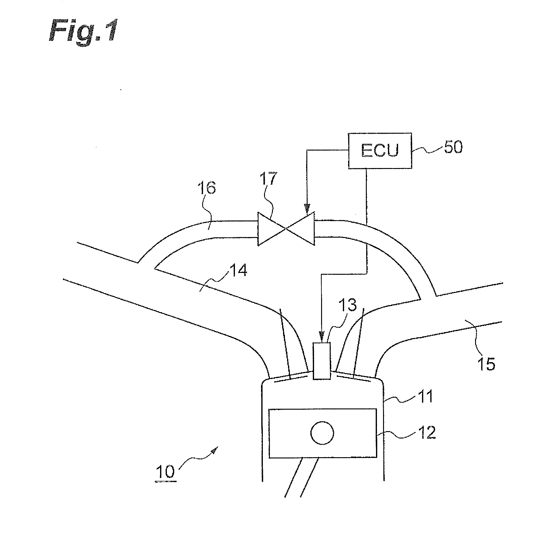
[0034]FIG. 1 is a view illustrating a configuration example of a compression ignition type internal combustion engine 10 according to an embodiment of the present invention. The compression ignition type internal combustion engine 10 includes a fuel injection apparatus. The fuel injection apparatus includes an injector 13 and an electronic control device 50. In FIG. 1, a configuration having only one cylinder is illustrated. However, the similar configuration is applied to a case having multiple cylinders. For example, the compression ignition type internal combustion engine 10 is a diesel engine which uses a piston-crank mechanism. In the compression ignition type internal combustion engine 10, air is sucked from an intake port 14 into a cylinder 11 in an intake stroke. The air sucked into the cylinder 11 is compressed by a piston 12 in a compression stroke. The intake air to be sucked in th...


PUM


Abstract

A fuel injection control apparatus of a compression ignition type internal combustion engine includes a controller adapted to control an injector so that pre-stage injection and post-stage injection are performed as fuel injection during one cycle. The controller controls an interval between the timing of the pre-stage injection and the timing of the post-stage injection so that an interval Δt1 between the timing of the pre-stage peak and the timing of the post-stage peak approximately satisfies a condition. The condition is that the interval Δt1 is 0.5 times an inverse number of the frequency f0 at which a combustion noise level becomes the maximum.

Description

BACKGROUND[0001]The present invention relates to a fuel injection control apparatus of a compression ignition type internal combustion engine. Particularly, the present invention relates to a technology which decreases combustion noise of a compression ignition type internal combustion engine.RELATED BACKGROUND ART[0002]As a method which decreases combustion noise of a compression ignition type internal combustion engine such as a diesel engine, there is a so-called pilot injection. The pilot injection is a method in which a small quantity of fuel is injected before a main injection. According to the pilot injection, it is possible to shorten ignition delay of the main injection. Japanese Unexamined Patent Application Publication No. 63-9657 discloses a technology related to the pilot injection. In this technology, overall combustion noise is decreased by examining pilot injection timing.[0003]Japanese Patent No. 3803903 discloses a technology which decreases a noise level of an int...

Claims


Application Information

Patent Timeline
IPC IPC(8): F02D41/40F02D41/38
CPCF02D41/403F02D2041/389F02D41/38F02D35/023F02D41/1497F02D41/401F02D41/402F02D41/405F02D2041/288Y02T10/40
Inventor KUZUYAMA, HIROSHIUMEHARA, TSUTOMUFUYUTO, TAKAYUKITAKI, MASAHIRO
Owner TOYOTA IND CORP
Why Eureka
Try Eureka