Method and apparatus for preparing a contoured biological tissue

a biological tissue and contouring technology, applied in the direction of prosthesis, electric/magnetic/electromagnetic heating, manufacturing tools, etc., can solve the problems of biological tissue thickness variation, inability to reduce the delivery profile to a desired size, and the delivery profile of the bioprosthetic implant and the delivery devi

Active Publication Date: 2015-04-02
EDWARDS LIFESCIENCES CORP
View PDF4 Cites 16 Cited by
  • Summary
  • Abstract
  • Description
  • Claims
  • Application Information

AI Technical Summary

Benefits of technology

[0014]The first elevation can be higher relative to the second elevation, or the second elevation can be higher relative to the first elevation.
[0015]The assembly can further comprise a spacer disposed between the first and second plates, the spacer controlling a thickness of the compressed biological tissue. A blade corresponding substantially to the defined shape on the first plate can also be included. The energy delivered by the one or more energy sources is preferably one or a combination selected from the group consisting of: thermal, ultrasound, electromagnetic, vibrational, hydraulic, piezoelectric, pneumatic, and acoustic and sound energy. In one embodiment, the energy is thermal energy and the ...

Problems solved by technology

One limitation of percutaneous procedures is the delivery profile of the bioprosthetic implant and delivery device.
Crimping, however, may not reduce the delivery profile to a desired size due to the inherent bulk or configuration of the bioprosthetic implant.
Additionally, biological tissue will typically exhibit variations in thicknesses and these variations often produce unpredictable results with respect to the delivery profile of the crimped valves.
While the use of artificial or polymeric materials can offer a greater degree of control and flexibility to the resulting thickness of the material used for bioprosthetic implants, such materials may not...

Method used


Image

  • Method and apparatus for preparing a contoured biological tissue
  • Method and apparatus for preparing a contoured biological tissue
  • Method and apparatus for preparing a contoured biological tissue

Examples


Embodiment Construction

[0042]Specific, non-limiting embodiments of the apparatus and methods for contouring bioprosthetic tissue will now be described with reference to the drawings. It should be understood that such embodiments are by way of example only and merely illustrative of but a small number of embodiments within the scope of the present disclosure. Various changes and modifications obvious to one skilled in the art to which the present disclosure pertains are deemed to be within the spirit, scope and contemplation of the present disclosure as further defined in the appended claims.

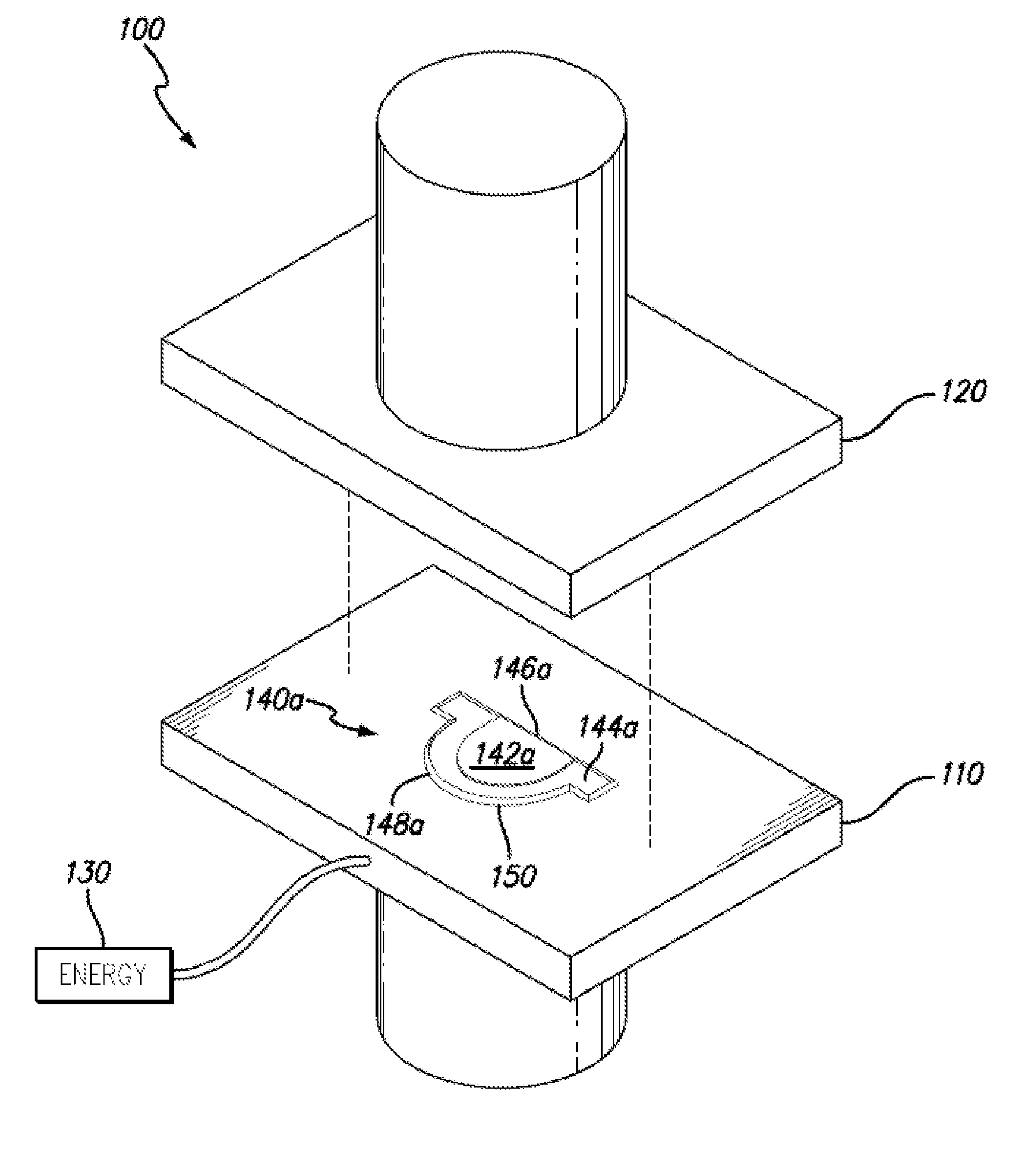
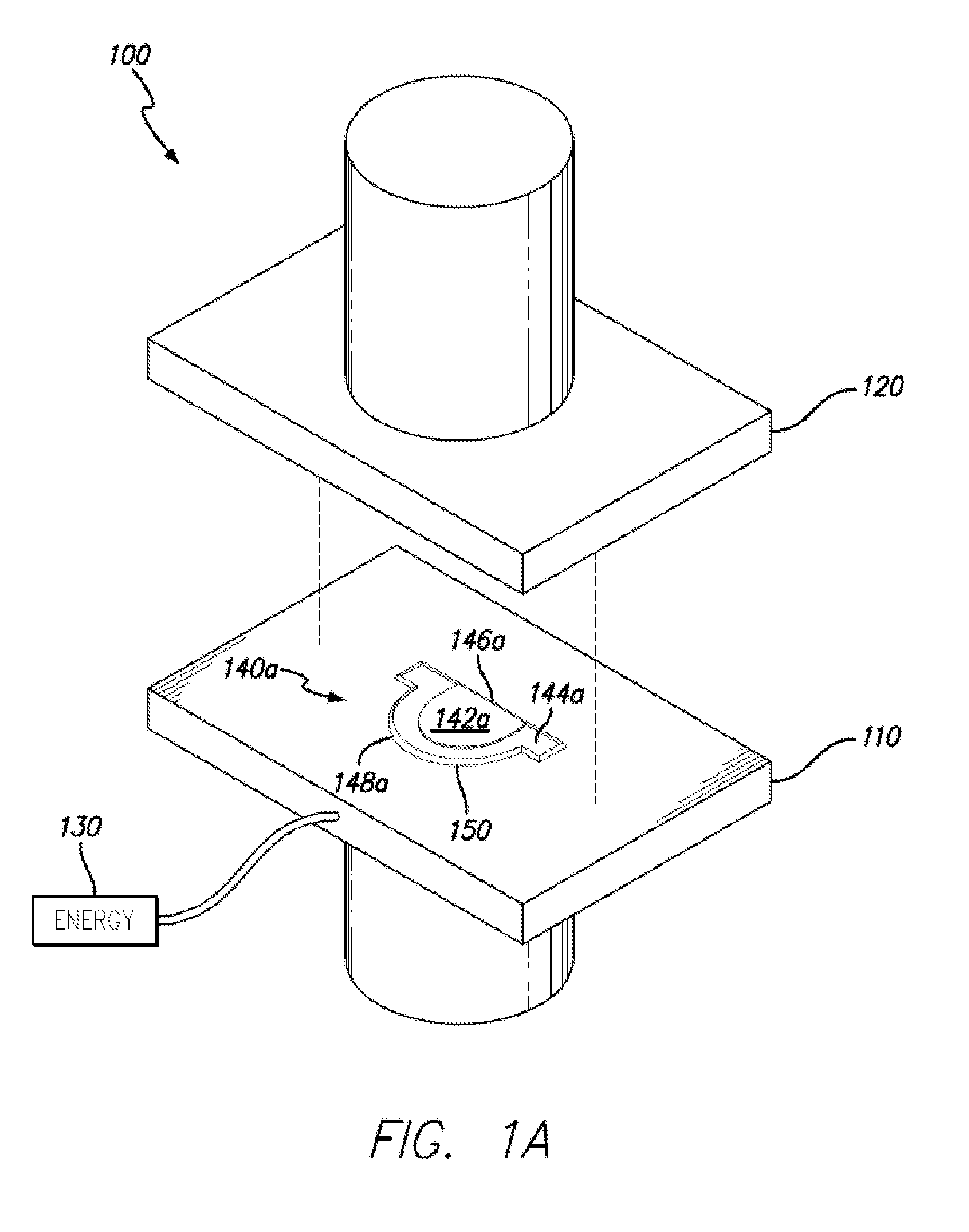
[0043]FIGS. 1A depicts an energized tissue compression assembly 100 comprising a first bottom plate 110 and a second top plate 120. Each one of the first and second plates 110, 120 is coupled to an actuator (not depicted) which controllably displaces the first and second plates 110, 120 towards one another in direct physical contact and away from one another to release the compressed tissue (not shown).

[0044]Either one...


PUM

PropertyMeasurementUnit
Fractionaaaaaaaaaa
Thicknessaaaaaaaaaa
Forceaaaaaaaaaa

Abstract

An assembly and methods for providing a contoured biological tissue are described. The assembly comprises a first plate and a second plate. The first plate is configured to receive a biological tissue. The second plate is configured to apply a compressive force on the biological tissue that is disposed on the first plate. One or both of the first and second plates comprise a defined shape and a contoured area within the defined shape. The contoured area comprises at least first and second elevations and a continuous transition between the first and second transitions. One or more energy sources is associated with one or both of the first and second plates. The one or more energy sources delivers energy while the second plate applies the compressive force on the biological tissue disposed on the first plate.

Description

FIELD OF THE INVENTION[0001]The present invention is directed to methods for treating bioprosthetic tissue for implantation in a patient and, more particularly, to methods for contouring and shaping biological tissue for use in connection with a bioprosthetic implant.BACKGROUND[0002]Minimally-invasive or percutaneous techniques for implanting bioprosthetic implants are commonly used in vascular and cardiovascular procedures. Such techniques involve the use of a delivery device, such as a catheter, to access a desired location via the patient's vasculature rather than using an open surgical approach where internal organs or tissue are exposed. The benefit of percutaneous procedures is in the ease of introducing devices into the patient without large cut downs, which can lead to long recovery times for patients.[0003]One limitation of percutaneous procedures is the delivery profile of the bioprosthetic implant and delivery device. Because access to the desired implantation site is gai...

Claims


Application Information

Patent Timeline
IPC IPC(8): A61F2/24
CPCA61F2230/0093A61F2/2415A61F2240/004A61F2/2412
Inventor MUNNELLY, AMY E.DOVE, JEFFREY S.LEE, MINSEY
Owner EDWARDS LIFESCIENCES CORP
Why Eureka
Try Eureka