Method and devices for compensating for path asymmetry

a path asymmetry and path technology, applied in the field of path asymmetry estimation and compensation, can solve the problems of inability of end-to-end tcs to solve this kind of asymmetry, communication paths are not perfectly symmetric, and timing support mechanisms are unable to correct for delay, so as to achieve the effect of minimal forward delay and minimal reverse delay

Active Publication Date: 2015-04-02
BRITISH TELECOMM PLC +2
View PDF5 Cites 30 Cited by
  • Summary
  • Abstract
  • Description
  • Claims
  • Application Information

AI Technical Summary

Benefits of technology

[0017]An exemplary embodiment of the invention provides a method of estimating asymmetric delays in communications between a master device and a slave device connected by a network, the method including the steps of: sending to the slave device first and second timing messages from the master device and respective first and second timestamps being the time of sending of the first and second messages according to the master clock; recording as third and fourth timestamps the time of receipt of the first and second messages at the slave device according to the slave clock; sending third and fourth timing messages to the master device from the slave device and recording as fifth and sixth timestamps the time of sending of the third and fourth messages according to the slave clock; recording as seventh and eighth timestamps the time of receipt of the third and fourth messages at the master device according to the master clock; sending, from the master device to the slave device, the seventh and eighth timestamps; calculating from said first to fourth timestamps a forward displacement factor which is the difference between the interval between the sending of said first and second timing messages and the interval between the receipt of said first and second timing messages; maintaining a total sum of said forward displacement factors since a predetermined point in time; estimating the total forward delay experienced by the timing messages sent from the master device to the slave device as equal to said total sum; estimating a minimum forward delay experienced by timing messages sent from the master device to the slave device; estimating the forward queuing delay as the difference between the estimated total forward delay and the estimated minimum forward delay; calculating from said fifth to eighth timestamps a reverse displacement factor which is the difference between the interval between the sending of said third and fourth timing messages and the interval between the receipt of said third and fourth timing messages; maintaining a total sum of said reverse displacement factors since a predetermined point in time; estimating the total reverse delay experienced by the timing messages sent from the master device to the slave device as equal to said total sum; estimating a minimum reverse delay experienced by timing messages sent from the salve device to the master device; and estimating the reverse queuing delay as the difference between the estimated total forward delay and the estimated minimum reverse delay.

Problems solved by technology

In real life, the communication paths are not perfectly symmetric mainly due to dissimilar forward and reverse physical link delays and queuing delays.
This “delay asymmetry” has become a major challenge in clock synchronization.
End-to-end TCs would not solve this kind of asymmetry.
However, even these timing support mechanisms are unable to correct for delay asymmetry due to dissimilar physical links between network elements.
If this difference is not properly compensated, even with the use of BCs, a static time error can accumulate over a chain of BCs.
Over multiple fiber links, the accumulated time error can become significant enough to exceed the very tight tolerances required by some applications such as those in mobile networks.
The above mechanisms are also unable to correct for delay asymmetries arising from the timing distribution inside an individual node.
These time errors are due to various internal asymmetric delays when a time reference is being distributed from a centralized module in a node (e.g., system card) to other modules in a node (e.g., line card).
These time errors arise, for example, due to the length of backplane traces, connectors, and various logic functions.

Method used


Image

  • Method and devices for compensating for path asymmetry
  • Method and devices for compensating for path asymmetry
  • Method and devices for compensating for path asymmetry

Examples


Embodiment Construction

[0025]Accordingly, at their broadest, methods of the present invention provide for estimating the asymmetric delays in communications between a master device and a slave device based on the intervals between the sending of timing messages and the receipt of the timing messages by the respective devices.

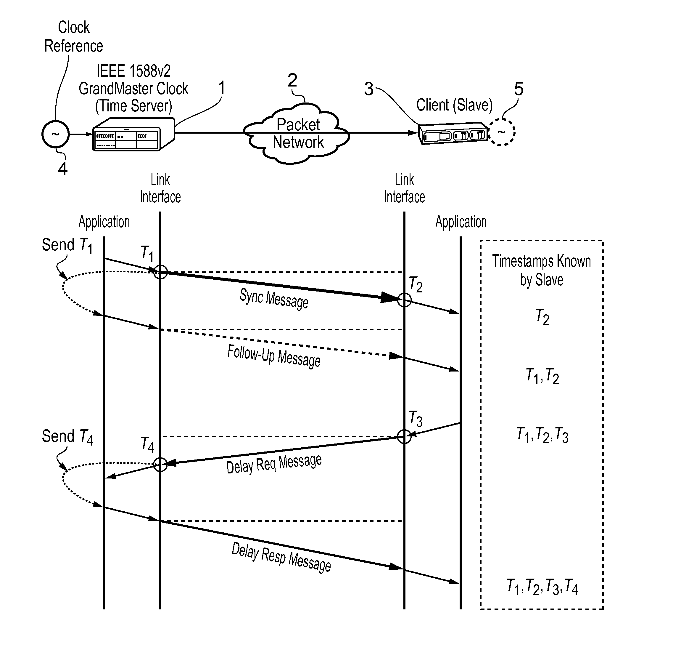
[0026]A first aspect of the present invention provides a method of estimating asymmetric delays in communications between a master device and a slave device connected by a network, the method including the steps of: sending to the slave device first and second timing messages from the master device and respective first and second timestamps being the time of sending of the first and second messages according to the master clock; recording as third and fourth timestamps the time of receipt of the first and second messages at the slave device according to the slave clock; sending third and fourth timing messages to the master device from the slave device and recording as fifth and sixth...


PUM


Abstract

This invention relates to methods and devices for compensating for path asymmetry, particularly with reference to time and frequency synchronization. The invention has particular application where time and frequency synchronization over packet networks using, for example, the IEEE 1588 Precision Time Protocol (PTP) is being carried out. Typically communication path delays between a time server (master) and a client (slave) are estimated using the assumption that the forward delay on the path is the same as the reverse delay. As a result, differences between these delays (delay asymmetries) can cause errors in the estimation of the offset of the slave clock from that of the master. Embodiments of the invention provide techniques and devices for compensating for path delay asymmetries that arise when timing protocol messages experience dissimilar queuing delays in the forward and reverse paths.

Description

FIELD OF THE INVENTION[0001]The present invention relates to methods and devices for estimating and compensating for path asymmetry. It is particularly, but not exclusively, concerned with estimating and compensating for path asymmetry where time and frequency synchronization over packet networks using, for example, the IEEE 1588 Precision Time Protocol (PTP) is being carried out.BACKGROUND OF THE INVENTION[0002]Timing transfer using a protocol such as IEEE 1588 PTP and a well designed slave clock recovery mechanism can provide time synchronization in the sub-microsecond region and lower. However, this is typically done using the important assumption that the time delay from master to slave is equal to that from slave to master.[0003]In real life, the communication paths are not perfectly symmetric mainly due to dissimilar forward and reverse physical link delays and queuing delays. Even in cases where the physical link delays are known and properly compensated for during clock sync...

Claims


Application Information

Patent Timeline
Patent Type & Authority Applications(United States)
IPC IPC(8): H04J3/06
CPCH04J3/0667
Inventor AWEYA, JAMESCHALOUPKA, ZDENEK
Owner BRITISH TELECOMM PLC
Why Eureka
Try Eureka