

Method for producing a stranded inner conductor for coaxial cable, and coaxial cable
a coaxial cable and inner conductor technology, applied in the direction of insulated conductors, power cables, cables, etc., can solve the problems of litz inner conductors spreading out at curvatures, deterioration of transmission properties, and affecting the service life of the cable, so as to reduce the loss, avoid the damage to the coating of individual wires, and reduce the effect of rl spikes
- Summary
- Abstract
- Description
- Claims
- Application Information
AI Technical Summary
Benefits of technology
Problems solved by technology
Method used
Image

Examples
Embodiment Construction
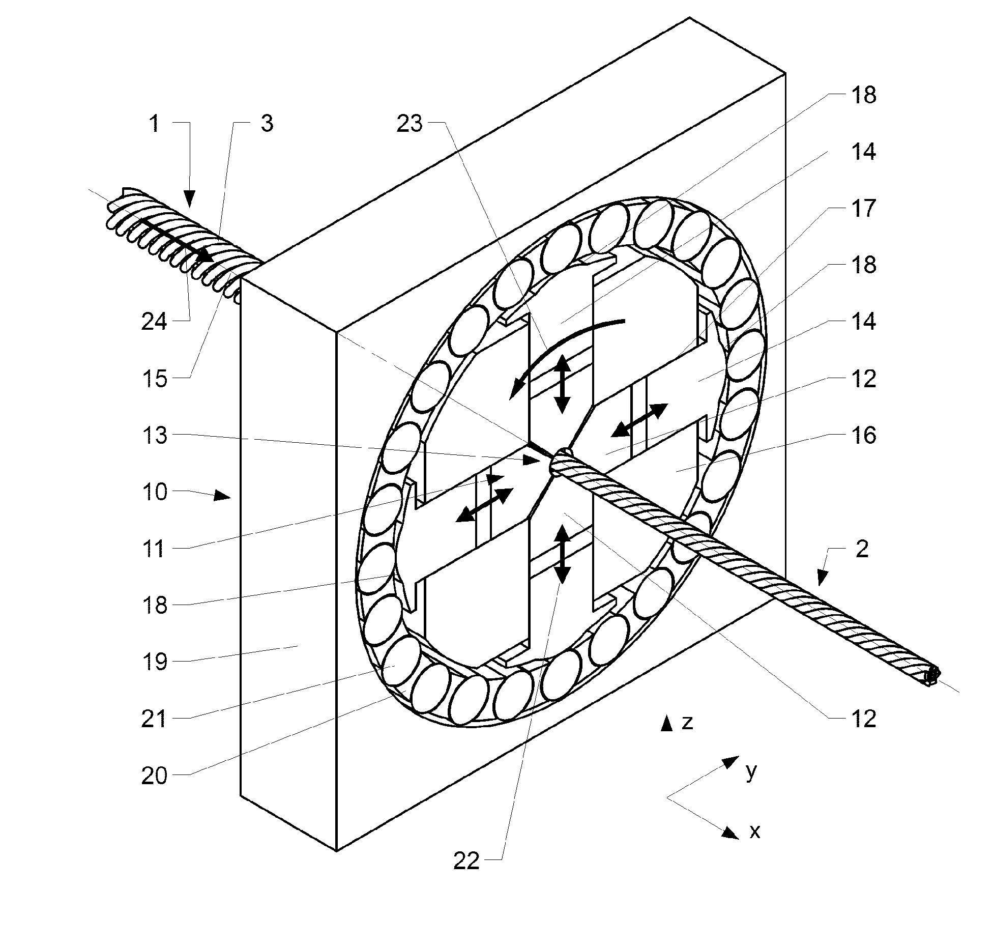
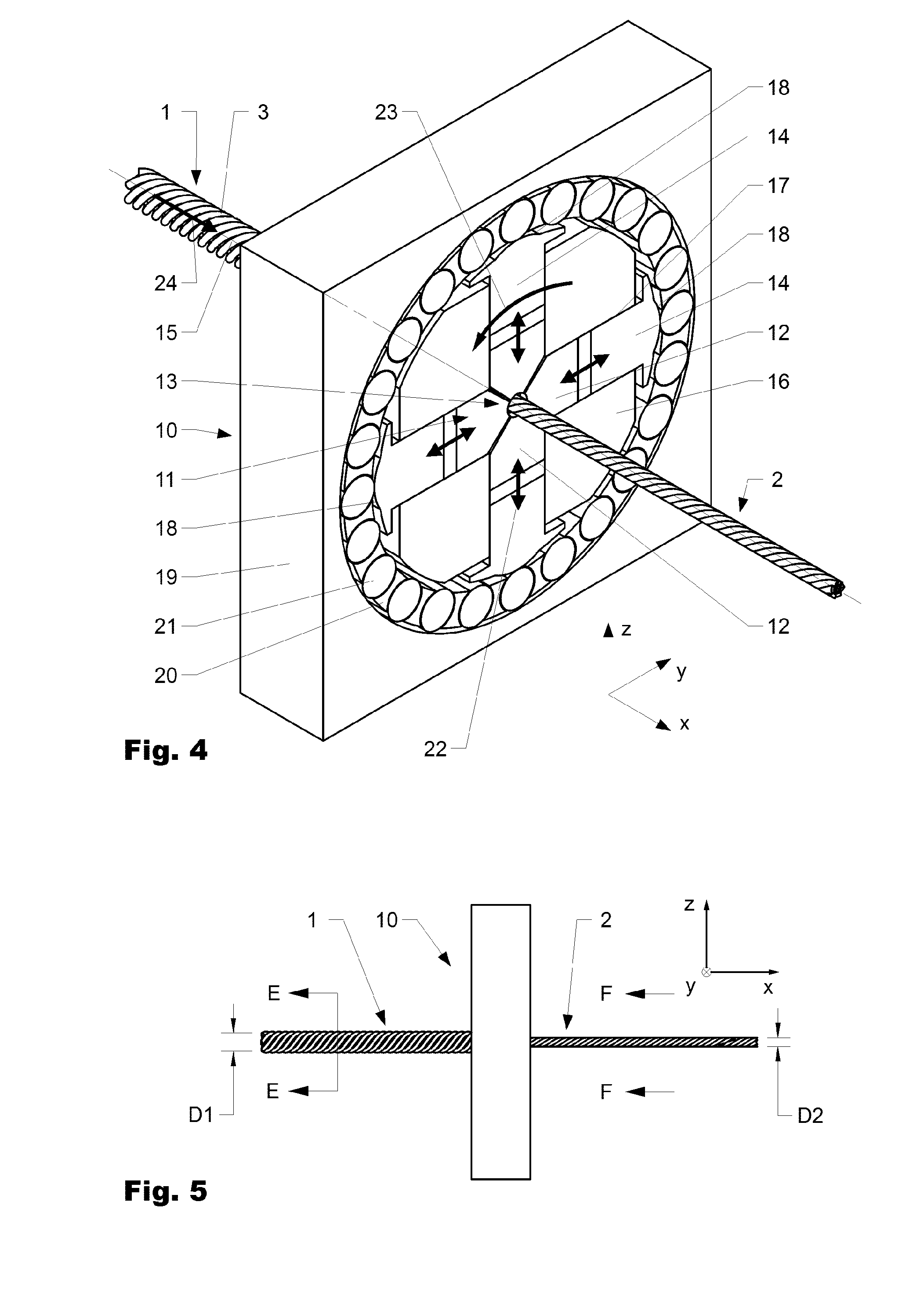
[0053]In the method according to the invention, the litz inner conductor I is deformed into the processed litz inner conductor 2 by means of a rotary swaging device 10.
[0054]FIG. 6a is a photograph of a cross section (micrograph) of a conventional stranded litz inner conductor 1. FIG. 6b is a graphical view of the same cross section. FIG. 7a is a photograph of a cross section (micrograph) of a rotary swaged litz inner conductor 2 according to the invention. FIG. 7b is a graphical view of the same cross section.
[0055]When comparing the sectional images of FIGS. 6 and 7, it is apparent that prior to the rotary swaging (cf. FIG. 6a or 6b) wires 3 are arranged comparatively loosely and at a large spacing with respect to one another and do not necessarily abut one another. In addition, the litz inner conductor 1 comprises an irregular and bumpy outer face 8.
[0056]By contrast, the wires 3 in the rotary swaged litz inner conductor 2 according to FIG. 7a or 7b are arranged so as to closely ...
PUM
| Property | Measurement | Unit |
|---|---|---|
| diameter | aaaaa | aaaaa |
| diameter | aaaaa | aaaaa |
| transmission frequencies | aaaaa | aaaaa |
Abstract
Description
Claims
Application Information