Stack of laminations and method for the production thereof

Active Publication Date: 2015-04-09
KIENLESPIESS GMBH
View PDF2 Cites 21 Cited by
  • Summary
  • Abstract
  • Description
  • Claims
  • Application Information

AI Technical Summary

Benefits of technology

[0020]The makes it possible to fabricate stacks of laminations with the highest streng

Problems solved by technology

In particular thin materials less than 0.5 mm thick benefit from the use of adhesive bonding as the joining technology, because the precision of the tools and machines norma

Method used


Image

  • Stack of laminations and method for the production thereof
  • Stack of laminations and method for the production thereof
  • Stack of laminations and method for the production thereof

Examples


Embodiment Construction

[0059]An exemplary embodiment will be used below to describe this technology in detail. The stacks of laminations are being exemplarily used for rotors and / or stators of electric motors.

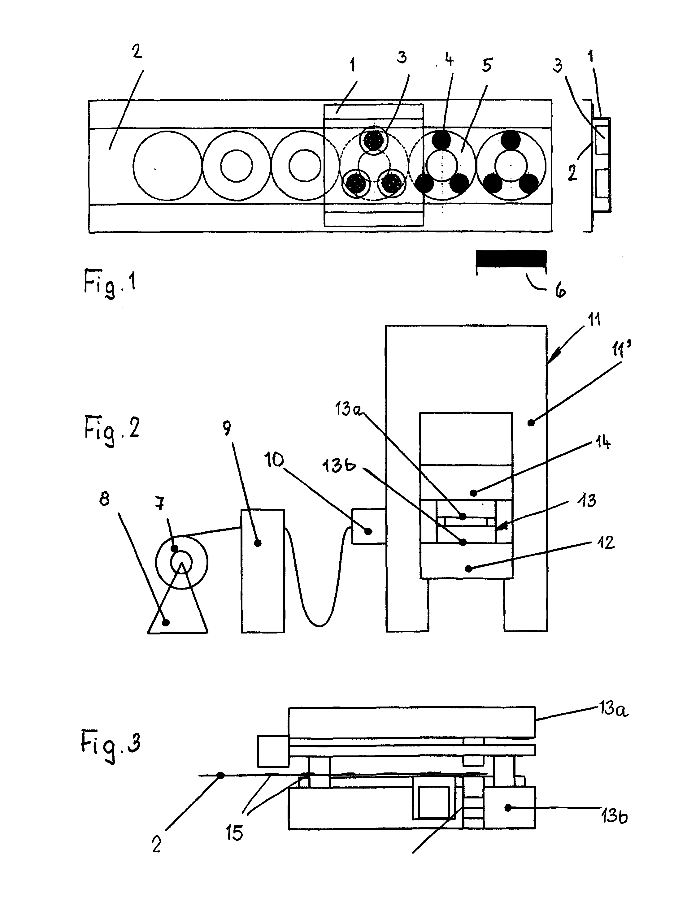
[0060]FIG. 2 shows a schematic view of a punch press. The decoiler 8 has a coil 7 of the starting material. As evident, the material is guided through a compensating sheave 9, and then in a feed device 10 and a press frame 11′ of a press 11. The tool 13 sits on a press table 12, and consists of two parts, an upper part 13a and a lower part 13b. An upper beam 14 of the press moves back and forth to punch laminations out of the strip-type material 2.

[0061]A few more details regarding the arrangement of key elements in the press frame are schematically denoted on FIG. 3. In this example, the application unit for the initiator is situated on the front side of the tool 13, and can be secured either to the upper 13a or lower 13b part of the tool 13. The application valve of the application unit operates wi...


PUM

PropertyMeasurementUnit
Temperatureaaaaaaaaaa

Abstract

The stack of laminations consists of punched laminations (5), which are bonded together by an adhesive agent. The adhesive agent is composed of an adhesive (4) and an initiator (15), which consists of methacrylates, derivative imines and methacrylic esters. The completely cured adhesive bond has long-term resistance when exposed to a temperature of at least over 80° C. The adhesive (4) is applied over the full surface area and in a contacting manner to one side of the lamination (5) and the initiator (15) is applied to the same side and/or to the other side of the lamination (5). The initiator (15) reacts with the adhesive (4) when contact is made and establishes the adhesive connection between laminations (5) lying against one another. The adhesive agent may, however, also be an adhesive (4) that cures by itself when heat is applied.

Description

FIELD / ABSTRACT OF GENERAL KNOWLEDGE[0001]The invention relates to a stack of laminations according to the preamble of claim 1 or 3, and to a method for manufacturing such a stack of laminations according to the preamble of claim 5 or 27.[0002]Electrical machines often use cores consisting of stacked laminations, which are fabricated out of cut electric sheets. A punch press is normally employed to cut out the individual laminations. The core or stack can be fabricated in various ways, to include mechanically joining the parts in the press to form cores, and welding, adhesively bonding or mechanically mating the laminations into stacks outside the press.BACKGROUND OF THE INVENTION / PRIOR ART[0003]DE 24 46 693 provides examples in the field of manufacturing stacks outside of the tool and press. This publication describes how to manufacture stacks of steel that has a thermosetting coating. EP 0 121 173 describes an approach to solving the problem in which the laminations are provided wi...

Claims


Application Information

Patent Timeline
IPC IPC(8): H02K1/18B32B38/00H02K1/28B32B27/30B32B27/38B32B27/40B32B37/12B32B7/14
CPCH02K1/18B32B37/1284B32B37/1292B32B38/0036B32B7/14B32B2457/00B32B27/38B32B27/40H02K1/28B32B2037/1253B32B27/308H02K15/02B21D28/02C08G59/4042H01F3/02H01F41/0233C09J163/00Y10T29/49078Y10T428/31515Y10T428/31551Y10T428/31938Y10T29/49009H01F3/04H02K15/12
Inventor BLOCHER, DANIELBAUER, STEFFENBARDOS, ANDRAS
Owner KIENLESPIESS GMBH
Why Eureka
Try Eureka