Unlock instant, AI-driven research and patent intelligence for your innovation.

Circuit device and electronic device

a circuit device and electronic technology, applied in the direction of pulse technique, oscillation generator, power conversion system, etc., can solve the problem of not being able to avoid through current dependen

Active Publication Date: 2015-04-09
SEIKO EPSON CORP
View PDF3 Cites 6 Cited by
  • Summary
  • Abstract
  • Description
  • Claims
  • Application Information

AI Technical Summary

Benefits of technology

This invention relates to a circuit device and electronic device that can adjust the dead time to be optimal. By setting appropriate delay times for each side of a bridge circuit using a delay setting register, the minimum required dead time can be achieved to avoid through current. The number of clocks can be used to consistently set the delay times and accurately measure the minimal dead time. The configuration simplifies the delay circuits.

Problems solved by technology

In the case where the bridge circuit is used in, for example, a motor driver apparatus, the optimal dead time varies according to the characteristics of the motor to be driven, and thus with the dead time being fixed, it may not be able to avoid through current depending on the type of motor.

Method used


Image

  • Circuit device and electronic device
  • Circuit device and electronic device
  • Circuit device and electronic device

Examples


Embodiment Construction

[0038]The following is a detailed description of a preferred embodiment of the invention. Note that the embodiment described below is not intended to unduly limit the content of the invention recited in the claims, and all of the constituent elements described in the embodiment are not necessarily essential as solutions provided by the invention.

1. Configuration Example

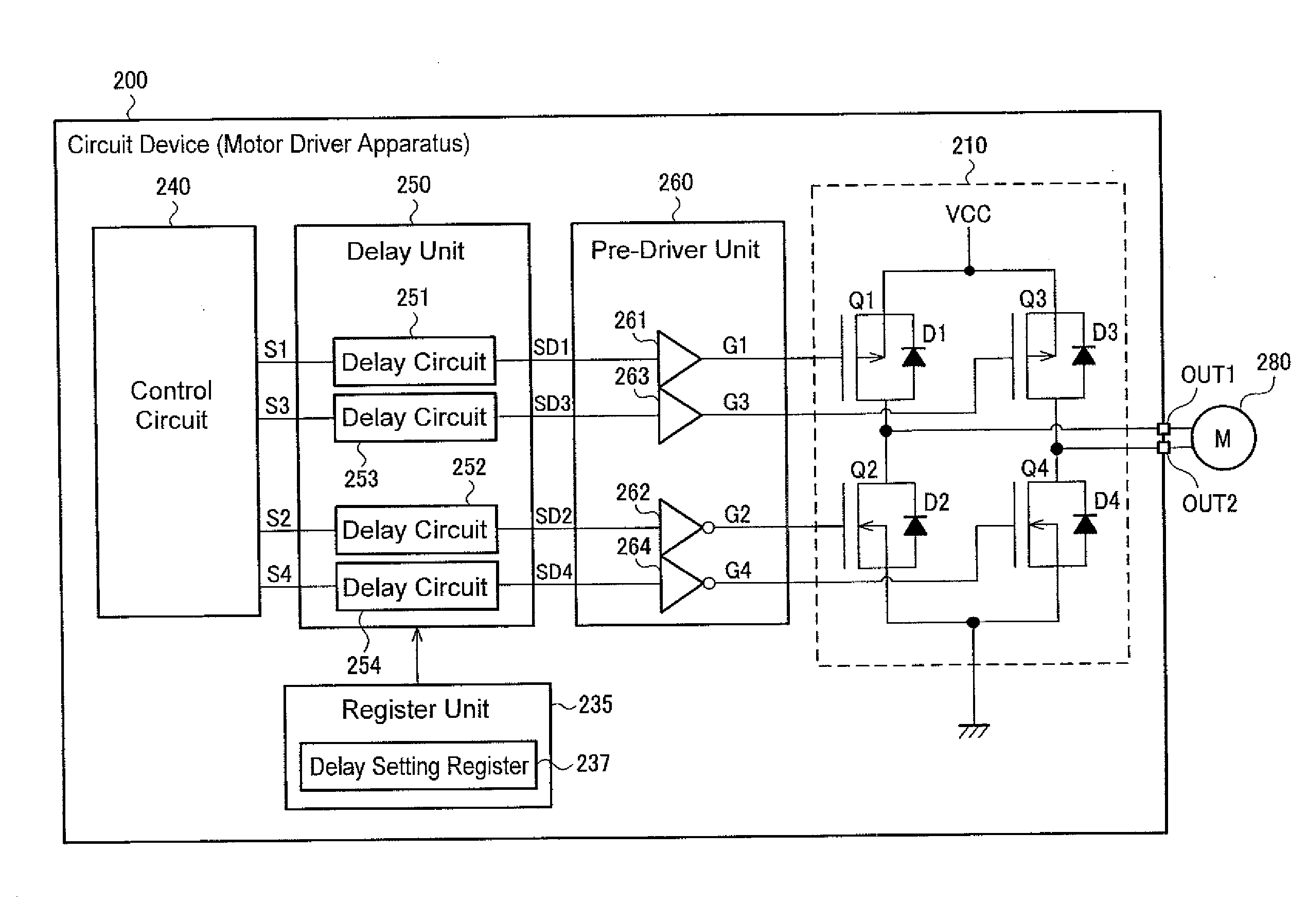
[0039]FIG. 1 shows an example of a configuration of a circuit device. A circuit device 200 includes a bridge circuit 210, a register unit 235, a control circuit 240, a delay unit 250, and a pre-driver unit 260. Hereinafter, an example will be described in which the circuit device 200 is used in a motor driver apparatus, but the circuit device 200 of the present embodiment is applicable to any apparatus that drives an external circuit by using the bridge circuit 210.

[0040]The bridge circuit 210 is a circuit that outputs driving current to a motor 280 (direct current motor) via terminals OUT1 and OUT2. To be specific, t...


PUM


Abstract

The invention provides a motor driver including pre-drivers for a bridge circuit, delay circuits, and a delay setting register, wherein in order to suppress short-circuit current caused at the time of signal switching in the bridge circuit, the delay circuits are set based on delay time information in the delay setting register so as to control signals input into the pre-drivers. The signals input into the individual pre-drivers are delayed differently by the delay circuits based on the delay time information in the delay setting register, thereby preventing a short-circuit current flow caused by an offset in the timing of the individual pre-drivers being turned on and off.

Description

BACKGROUND[0001]1. Technical Field[0002]The present invention relates to a circuit device, an electronic device, and the like.[0003]2. Related Art[0004]With a bridge circuit that drives an external circuit by turning transistors on and off, the timing of switching between on and off varies slightly from transistor to transistor when the transistors are switched between on and off during a transition period between a charge period and a decay period. If a period during which a high-side transistor and a low-side transistor are simultaneously turned on occurs due to the variation in timing, through current flows via the transistors that have been turned on simultaneously.[0005]In order to avoid such through current, JP-A-2008-289143 discloses a method in which a dead time is provided during which all transistors in a bridge circuit are turned off. The document also discloses a method for reducing switching noise during the dead time by monitoring the driving signals of the transistors...

Claims


Application Information

Patent Timeline
IPC IPC(8): H03K3/012
CPCH03K3/012H02M1/38H02M7/5387H02P7/29H02P7/04
Inventor TOMOHARA, KIYOHIDE
Owner SEIKO EPSON CORP