Polishing pad and method for making the same

a technology of polishing pad and surface, which is applied in the direction of lapping tool, manufacturing tool, metal-working apparatus, etc., can solve the problems of poor planarization performance of the grinding surface, insufficient overall strength, and short service life, and achieves high planarization efficiency, preferable surface quality, and high planarization efficiency

Active Publication Date: 2015-04-09
SAN FANG CHEM IND
View PDF6 Cites 10 Cited by
  • Summary
  • Abstract
  • Description
  • Claims
  • Application Information

AI Technical Summary

Benefits of technology

[0009]In the present invention, the polishing pad has preferable rigidity and provides high planarization efficiency, which makes it difficult to scratch a polished workpiece, so that the polished workpiece has preferable surface quality, and has a longer service life. Besides, the polishing pad also has preferable stability and reproducibility in the manufacturing process.

Problems solved by technology

A disadvantage of the polishing pad is that the flexibility thereof may easily lead to poor planarization performance of its grinding surface, and the resin cannot uniformly enclose the fibers, that is, a portion of the fibers are not enclosed by the resin, resulting in that the overall strength is insufficient and the service life is shorter.
However, the major problem of the polishing pad is that since it is difficult to achieve uniform distribution of the concentration of the resin in the cylindrical mold, non-uniform temperature distribution at positions in the cylindrical mold during the molding process may lead to different sizes and non-uniform distribution of the pores, which are not easy to be controlled, and as a result, after the slicing process, the difference between the sizes of the pores on the sliced surface of the polishing pad becomes more significant.
Moreover, the pores are not in communication with each other, and polishing slurry may not easily flow therebetween in use, and is apt to scratch a workpiece.

Method used


Image

  • Polishing pad and method for making the same
  • Polishing pad and method for making the same
  • Polishing pad and method for making the same

Examples


example 1

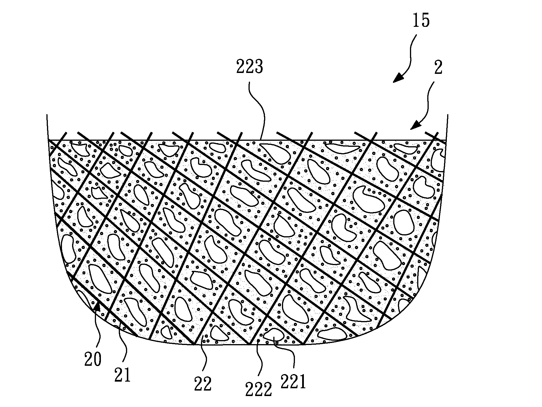
[0031]First, a non-woven fiber substrate having a thickness of 5.0 mm is provided, whose weight is 950 g / m2 and density is 0.19 g / cm3. The material of fibers of the non-woven substrate is 100% of PET, and the fineness thereof is 1.50 den.

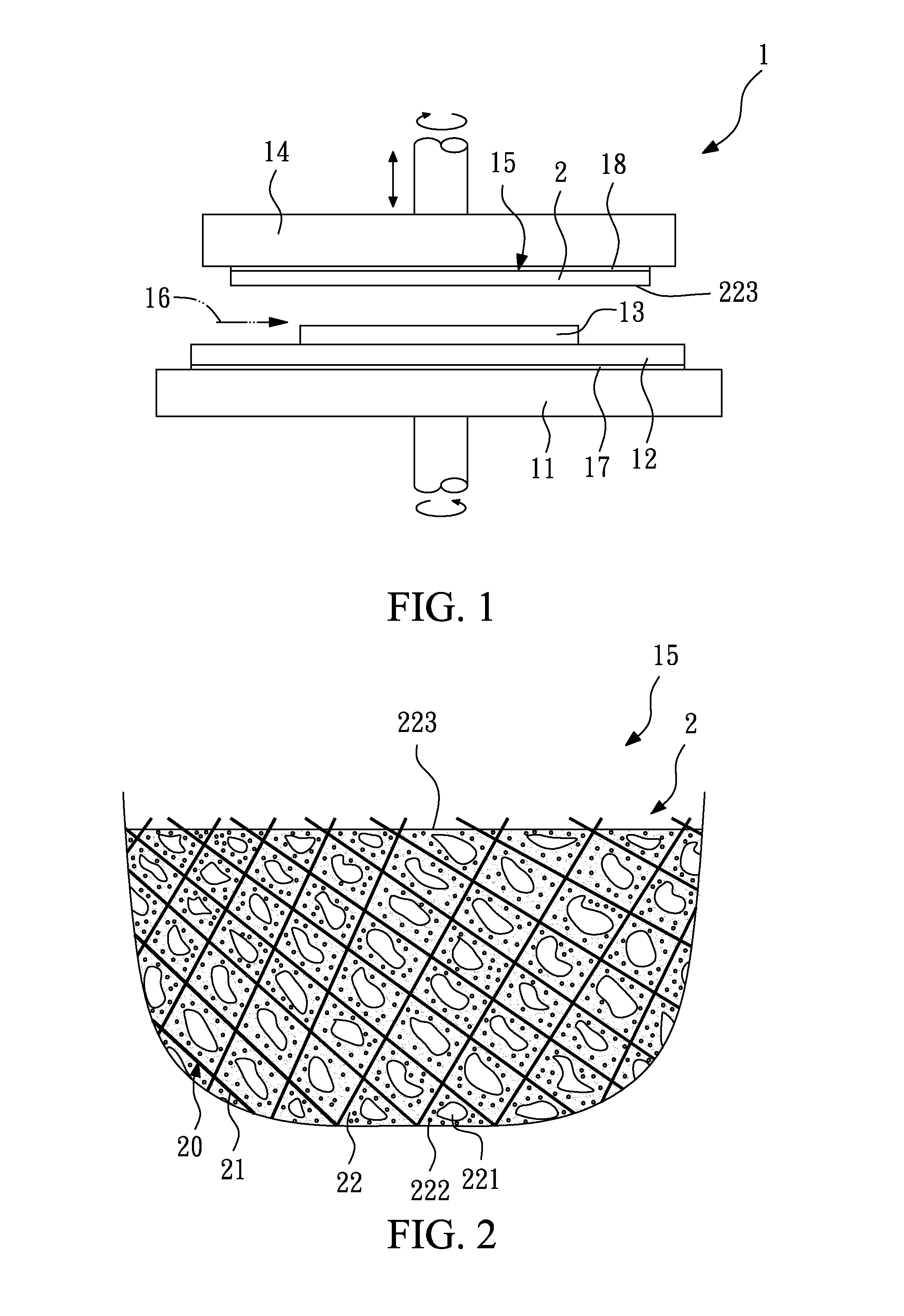
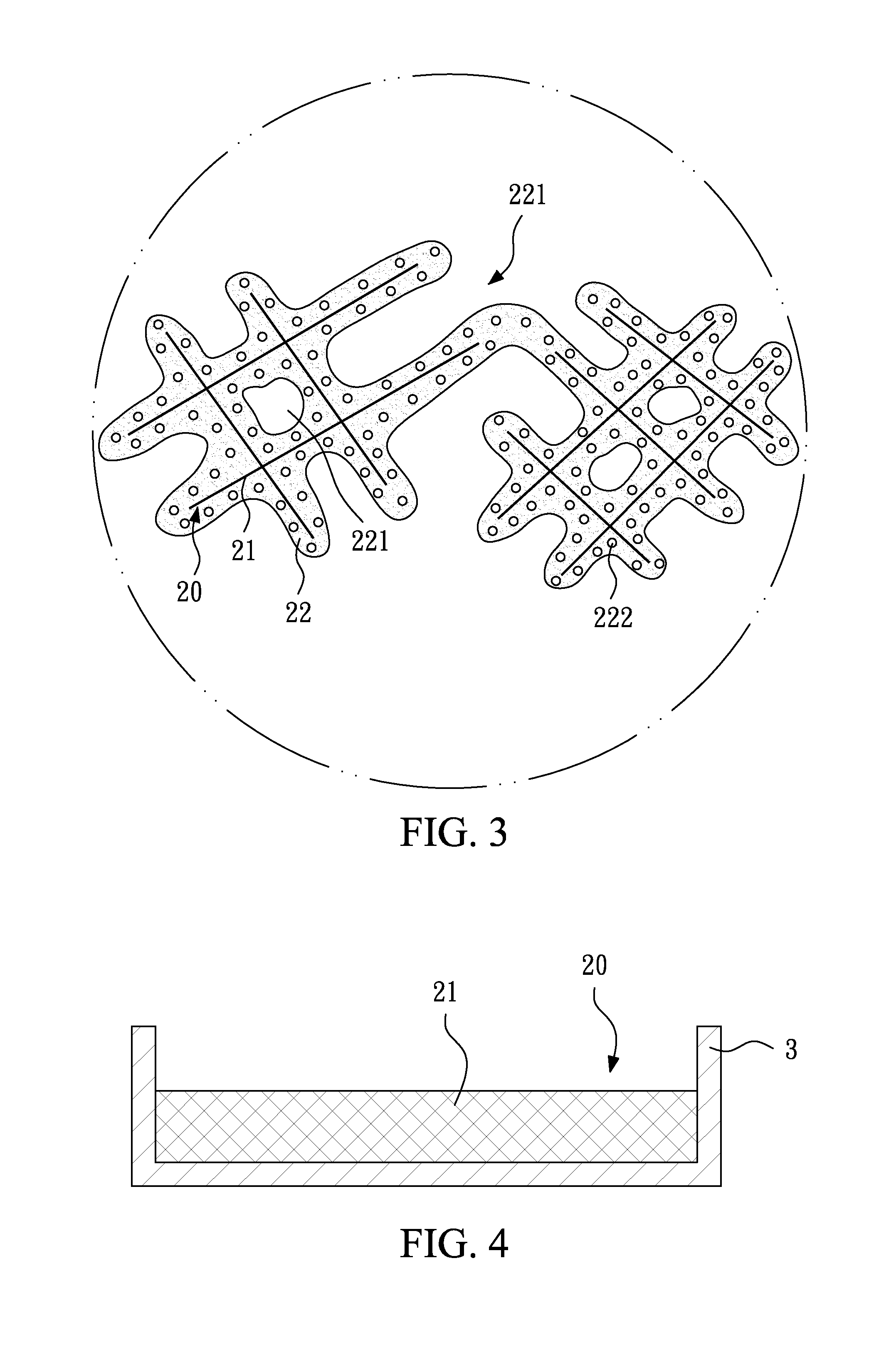
[0032]Next, the fiber substrate is placed in a mold, and in this embodiment, the length, the width and the depth of the mold are respectively 100 cm, 100 cm and 1 cm.

[0033]Then, diisocyanate (TDI component) with 78.00 wt % and an equivalent number of 200-450 and polyol with 22.00 wt % and an equivalent number of 50-250 are fully mixed to form a foaming resin. In the meantime, the foaming resin is mixed and stirred to form a polymer solution with viscosity of 2250 cps.

[0034]Next, the polymer solution of the foaming resin is injected into the mold to permeate the fiber substrate to enclose the fibers.

[0035]Then, a pre-aging step is performed, in which the foaming resin and the fiber substrate in the mold are directly heated to 70□, which is maintained...

example 2

[0037]First, a non-woven fiber substrate having a thickness of 4.5 mm is provided, whose weight is 675 g / m2 and density is 0.19 g / cm3. The material of fibers of the non-woven substrate is 60% of PET and 40% of Nylon, and the fineness thereof is 3.0 den.

[0038]Next, the fiber substrate is placed in a mold, and in this example, the length, the width and the depth of the mold are respectively 90 cm, 170 cm and 5 cm.

[0039]Then, diisocyanate (TDI component) with 74.20 wt % and an equivalent number of 200-450, a cross-linking hardener with 20.81 wt % and an equivalent number of 50-250 and polyol with 4.99 wt % and an equivalent number of 50-150 are fully mixed to form a foaming resin. In the meantime, the foaming resin is mixed and stirred to form a polymer solution with viscosity of 3600 cps.

[0040]Next, the polymer solution of the foaming resin is injected into the mold to permeate the fiber substrate to enclose the fibers.

[0041]Then, a pre-aging step is performed, in which the foaming re...

example 3

[0043]First, a non-woven fiber substrate having a thickness of 3.0 mm is provided, whose weight is 390 g / m2 and density is 0.13 g / cm3. The material of fibers of the non-woven substrate is 50% of PET and 50% of PP, and the fineness thereof is 2.5 den.

[0044]Next, the fiber substrate is placed in a mold, and in this embodiment, the length, the width and the depth of the mold are respectively 110 cm, 110 cm and 5 cm.

[0045]Then, diisocyanate (TDI component) with 68.90 wt % and an equivalent number of 200-450, aliphatic amine with 28.57 wt % and an equivalent number of 50-250 and polyol with 2.53 wt % and an equivalent number of 50-150 are fully mixed to form a foaming resin. In the meantime, the foaming resin is mixed and stirred to form a polymer solution with viscosity of 4400 cps.

[0046]Next, the polymer solution of the foaming resin is injected into the mold to permeate the fiber substrate to enclose the fibers.

[0047]Then, a pre-aging step is performed, in which the foaming resin and ...


PUM

PropertyMeasurementUnit
compression ratioaaaaaaaaaa
densityaaaaaaaaaa
compression ratioaaaaaaaaaa

Abstract

The present invention relates to a polishing pad and a method for making the same. The polishing pad has a grinding layer. The grinding layer includes a plurality of fibers and a main body. The fineness of the fibers is 0.001 den to 6 den. The main body is a foam and encloses the fibers. The main body has a plurality of first pores and a plurality of second pores, wherein the first pores are communicated with each other, and the second pores are independent from each other. The size of the first pores is at least 5 times greater than the size of the second pores. The hardness of the grinding layer is 30 to 90 shore D, and the compression ratio thereof is 1% to 10%.

Description

BACKGROUND OF THE INVENTION[0001]1. Field of the Invention[0002]The present invention relates to a polishing pad and a method for making the same, and in particular, to a polishing pad having a fiber substrate and a method for making the same.[0003]2. Description of the Related Art[0004]The conventional polishing pad substantially can be divided into two types: a non-woven polishing pad and a separate foam polishing pad. The conventional non-woven polishing pad includes a plurality of fibers and a resin, and the polishing pad is manufactured by using a composite material of the fibers (such as velvet or suede) and the resin, or impregnating a non-woven fabric formed by the fibers in a thermoplastic polyurethane resin for wet coagulation to form a flexible sheet having high deformability formed. A disadvantage of the polishing pad is that the flexibility thereof may easily lead to poor planarization performance of its grinding surface, and the resin cannot uniformly enclose the fiber...

Claims


Application Information

Patent Timeline
Patent Type & Authority Applications(United States)
IPC IPC(8): B24D11/02B24D3/32B24D11/00
CPCB24D11/02B24D3/32B24D11/006B24B37/24B24D11/00B24D11/001
Inventor FENG, CHUNG-CHIHYAO, I-PENGWU, WEN-CHIEHHUNG, YUNG-CHANG
Owner SAN FANG CHEM IND
Why Eureka
Try Eureka