Modular Isolation Systems

a module and isolation system technology, applied in the field of module isolation systems, can solve the problems of personal injury, death, property and environmental damage, and the use of this method alone can be quite expensive, and is not necessarily suitable for payload housing within a structure, etc., and achieves the effect of shortening the shallow ramp and high profil

Inactive Publication Date: 2015-04-16
WORKSAFE TECHNOLOGY INC
View PDF1 Cites 13 Cited by
  • Summary
  • Abstract
  • Description
  • Claims
  • Application Information

AI Technical Summary

Benefits of technology

[0028]An additional advantage to the low profile modular isolation system provided by the present invention involves the fact that payload items for which seismic isolation is desired must be loaded onto (and off of) the isolation platform or floor. When such items are heavy, it is difficult or impossible to lift them onto a raised floor or platform without mechanical assistance, and a ramp is often necessary. However, particularly within a confined container such as a cargo container or similarly sized structure there is little or no room for ramps permitting the loading of, for example, computer servers hard drive arrays and other similar equipment. Furthermore, in various locations governmental regulations require such ramps to have a maximum slope sufficiently shallow to permit disabled persons to easily access the top of the floor or platform in a wheelchair. The necessary length of such a ramp often it eliminates the possibility of using a ramp within a confined environment such as a cargo container or similarly sized structure.
[0029]Thus, in a preferred embodiment described in more detail herein, the present invention provides a seismic isolation system that may be constructed at floor level or at a level only slightly above floor level, thus permitting shorter shallow ramps to be used when necessary. The modular isolation system of the present invention may be constructed so that its top surface is substantially level with the floor or foundation surrounding it. In such a case, the floor foundation may be partly excavated to create a support for the modular isolation system at a level below that of the top surface of the floor or foundation. In this way, the top surface of the modular isolation system may be slightly above, or substantially coplanar with, the top surface of the floor or foundation, thereby permitting the loading and unloading of payload without the use of ramps.
[0030]A modular isolation system, whether of low or high profile, has additional advantages; these include the fact that isolation systems can be tailored for any of a vast variety of environments. Additionally, a variety of sizes of modular isolation system components may be provided to suit a variety of payload masses and construct isolation systems of the necessary calculated strength in view of the payload mass and the anticipated maximum seismic tremor which the system is made to withstand effectively.

Problems solved by technology

Although minor earthquakes are common, with thousands of smaller earthquakes occurring daily, larger magnitude seismic events can cause personal injury, death and property and environmental damage, particularly in heavily populated areas.
However, in addition to the relative unpredictability of damage caused by tremors of high magnitude and long duration and of the directionality of shaking, use of this method alone can be quite expensive and is not necessarily suitable for payloads to be housed within a structure.
Particularly for delicate, sensitive or easily damaged payload, this approach alone is not especially useful.
Such active systems are complex, and require service or routine maintenance.
Certain disadvantages to such pre-existing systems include the fact that it is difficult to establish the minimum acceleration at which the latch means is released; it is difficult to reset the latch means after the floor has been released; it may be difficult to restore the floor to its original position after it has moved in the horizontal direction; the dissipative or damping force must be recalibrated to each load; there is a danger of rocking on the vertical springs; and since the transverse rigidity of the vertical springs cannot be ignored with regard to the horizontal springs, the establishment of the horizontal springs and an estimate of their effectiveness, are made difficult.
However, the device disclosed is not designed to move horizontally in an acceleration-resisting manner.

Method used


Image

  • Modular Isolation Systems
  • Modular Isolation Systems
  • Modular Isolation Systems

Examples


examples

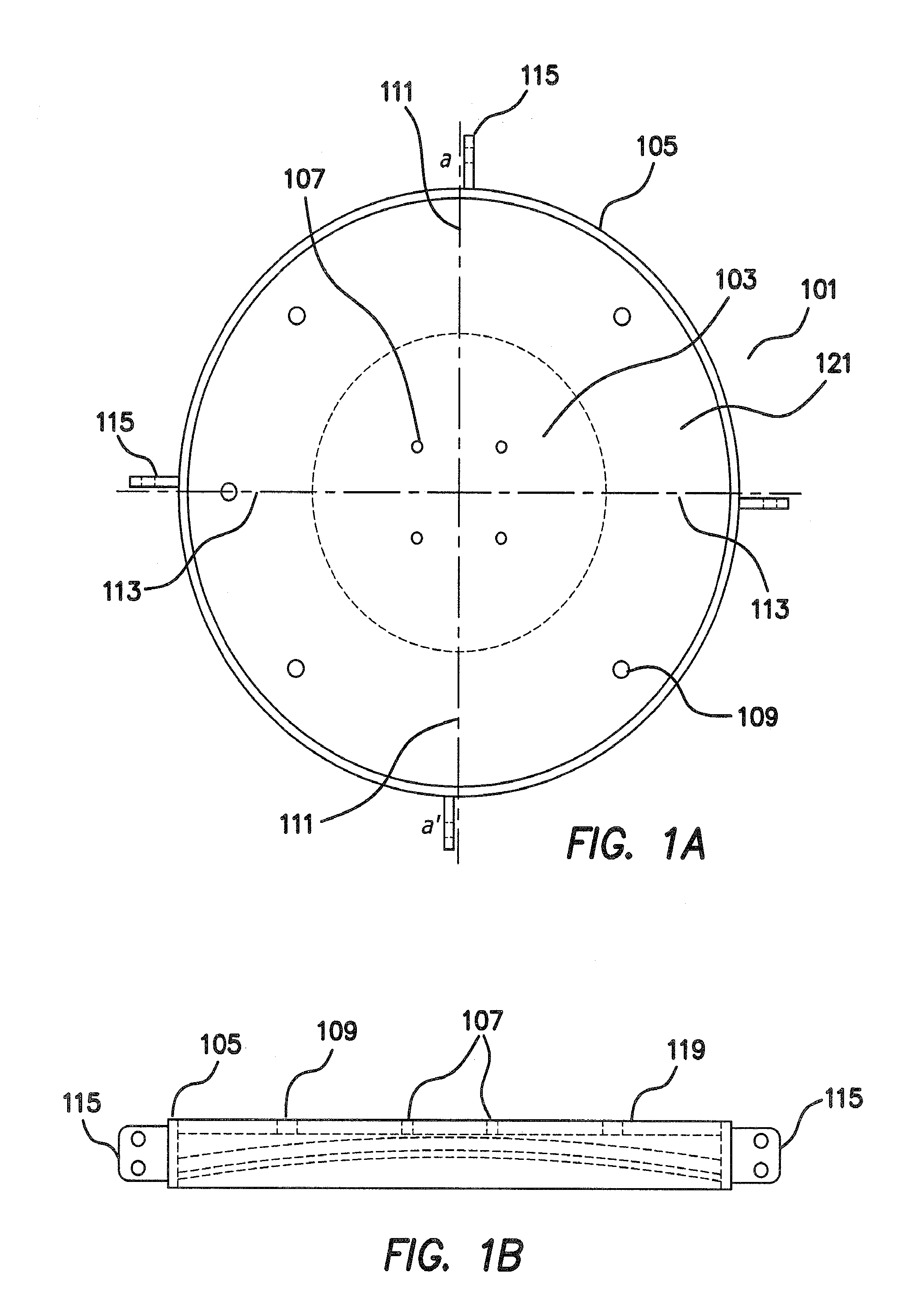
[0070]FIG. 1A depicts a view of a modular isolation bearing half (101) of the present invention, from the side opposing the load-bearing surface, and showing the features of the load-bearing surface underneath in a transparent dotted line. With respect to the load-bearing surface, the substantially circular central area is depicted at (103). This substantially circular central area preferably has a curved surface; in one preferred embodiment the central, spherically curved region has a radius of curvature of about 86 inches, meaning it corresponds to an arc of a circle having a radius of about 86 inches. The radius of the load-bearing surface itself is about 32 inches. However. the radius of the central, spherically curved region (103) will change as necessary when employing a different bearing have admitted having a different load bearing surface radius.

[0071]Still with reference to FIG. 1A, in a line segment extending from point a to point a′, the ratio of the diameter of the cent...


PUM


Abstract

A modular base isolation system suitable for constructing isolation floors and platforms using the same elements, and capable of scaling up or down to suit the payload mass. These systems are low profile and permit placement of such systems un paces having restricted headroom. Also kits and methods or making and using such modular isolation systems.

Description

RELATED APPLICATION[0001]This application claims priority to U.S. Provisional Patent Application No. 61 / 605,669, which was filed Mar. 1, 2012 and is hereby incorporated by reference herein in its entirety.BACKGROUND OF THE INVENTION[0002]Earthquakes occur at cracks in the earth's crust in which shifting tectonic plates build stresses within the crust that literally tear the surface of the earth when they are released. Generally speaking, the world's most active fault zones are known. The most famous of these fault zones is the so-called Pacific “ring of fire” circumscribing the Pacific Ocean and including most of the west coast of North, Central and South America, Japan, Taiwan, Indonesia, and New Zealand. Other fault zones occur in, for example, the eastern Mediterranean (e.g., Turkey, Armenia and the Caucasus region of Russia), and in South Asia (for example, Pakistan, Malaysia and Thailand).[0003]Although minor earthquakes are common, with thousands of smaller earthquakes occurri...

Claims


Application Information

Patent Timeline
Patent Type & Authority Applications(United States)
IPC IPC(8): E04B1/36E04F15/024E04H9/02E04B1/98
CPCE04B1/36E04B1/98E04F15/02405E04F15/02452E04F15/02458E04H9/023E04H9/0237F16F15/021F16F2230/14E01D19/04E04H9/024E04H9/028F16F15/02
Inventor MORENO, GIL A.HUBBARD, DON A.
Owner WORKSAFE TECHNOLOGY INC
Why Eureka
Try Eureka