Systems and Methods for Bypassing a Coalescer in a Gas Turbine Inlet

a gas turbine and coalescer technology, applied in the field of gas turbine inlet air treatment systems, can solve the problems of compressor surge, compressor air flow decrease, compressor operation efficiency reduction,

Inactive Publication Date: 2015-04-16
BHA ALTAIR
View PDF3 Cites 124 Cited by
  • Summary
  • Abstract
  • Description
  • Claims
  • Application Information

AI Technical Summary

Benefits of technology

[0007]The disclosure provides a solution to the problem of high...

Problems solved by technology

Over time, the pressure drop across the coalescers may increase resulting in a decrease in the amount of air flow provided to the compressor.
This decrease reduces the operating effi...

Method used


Image

  • Systems and Methods for Bypassing a Coalescer in a Gas Turbine Inlet
  • Systems and Methods for Bypassing a Coalescer in a Gas Turbine Inlet
  • Systems and Methods for Bypassing a Coalescer in a Gas Turbine Inlet

Examples


Embodiment Construction

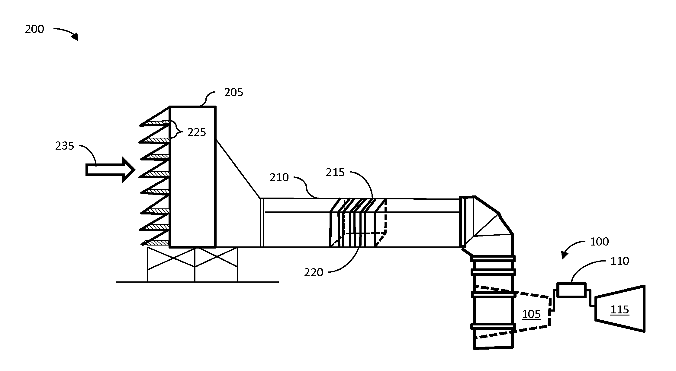
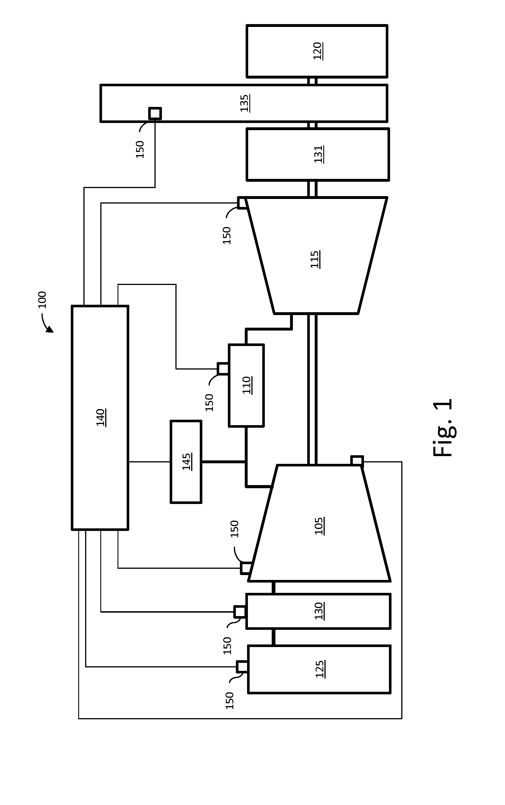
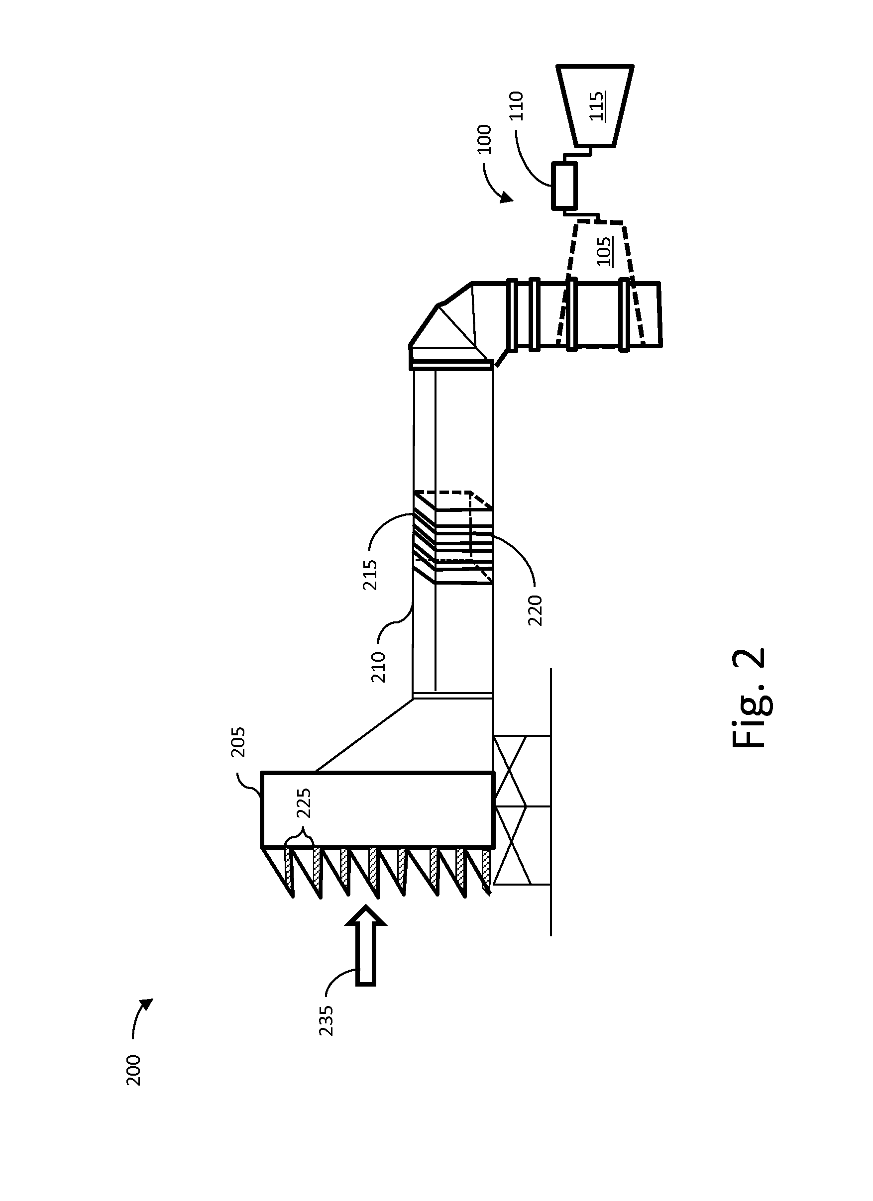
[0018]Referring now to the drawings, FIG. 1 illustrates a simplified, schematic depiction of one embodiment of a gas turbine system 100. In general, the gas turbine system 100 may include a compressor 105, one or more combustor(s) 110 and a turbine 115 drivingly coupled to the compressor 105. During operation of the gas turbine system 100, the compressor 105 supplies compressed air to the combustor(s) 110. The compressed air is mixed with fuel and then burned within the combustor(s) 110. Hot gases of combustion flow from the combustor(s) 110 to the turbine 115 in order to turn the turbine 115 and generate work, for example, by driving a generator 120.

[0019]Additionally, the gas turbine system 100 may include an inlet duct 125 configured to feed ambient air and possibly injected water to the compressor 105. The inlet duct 125 may have ducts, filters, coalescers, screens and / or sound absorbing devices that contribute to a pressure loss of ambient air flowing through the inlet duct 125...


PUM

PropertyMeasurementUnit
Pressureaaaaaaaaaa

Abstract

A system including an air intake subsystem having a housing is provided. A coalescer having a frame is disposed inside the housing. The system includes a mounting bracket, and a release mechanism coupled to the frame and the mounting bracket. The release mechanism is adapted to selectively release the frame.

Description

TECHNICAL FIELD[0001]The subject matter disclosed herein generally relates to inlet air treatment systems, and more specifically to systems and methods for bypassing panel or pocket coalescers for gas turbine systems.BACKGROUND[0002]Gas turbine systems typically include a compressor for compressing incoming air, a combustor for mixing fuel with the compressed air and igniting a fuel and air mixture to form a high temperature gas stream, and a turbine section driven by the high temperature gas stream.[0003]The gas turbine system may be a component in a gas turbine plant such as a power plant for the production of electricity. In some cases the gas turbine system may be used in a combined cycle power plant. In a combined cycle power plant, the gas turbine system generates power and electricity from the combustion of the mixture of fuel and air. The heat energy from this combustion is transmitted to a heat recovery steam generator, which converts the heat into steam. The steam is then ...

Claims


Application Information

Patent Timeline
IPC IPC(8): F02C7/05F02M35/08F02M35/024
CPCF02C7/05F02M35/024F02M35/082B01D46/0087B01D46/0095B01D2273/14
Inventor JARRIER, ETIENNE RENEHATFIELD, MARTIN GREGORYKIENITZ, PAUL MICHAEL
Owner BHA ALTAIR
Why Eureka
Try Eureka