Cutting apparatus including a wire cutting member

a cutting device and cutting member technology, applied in the field of cutting equipment, can solve the problems of large space occupation, large size of cutting apparatus, and large weight of bulky wire saws, and achieve the effect of greater cutting apparatus width

Active Publication Date: 2015-04-16
ILLINOIS TOOL WORKS INC
View PDF24 Cites 23 Cited by
  • Summary
  • Abstract
  • Description
  • Claims
  • Application Information

AI Technical Summary

Benefits of technology

[0015]In one aspect, the width of the cutting apparatus may be greater when in the second position.

Problems solved by technology

Wire saws are bulky items and may be unsafe to operate.
The bulky wire saws are limited in the environments in which they may be operated and consume large spaces when not in use.
Moreover, wire saws may not adequately couple to pipes or the operator may operate the wire saw in an unsafe position, thereby putting the operator in danger when operating the wire saws.
Conventional cutting apparatuses and wire saws may not fit through a manhole, thereby precluding such conventional cutting apparatuses and wires saws from being used in subterranean environments.
Excessive quantities of heat can undesirably damage the cutting member 24 and / or components of the cutting apparatus 20.
Excessive debris buildup in the cutting apparatus 20 may negatively affect operation of the cutting device and / or damage the cutting apparatus 20.
Conventional cutting apparatuses may be too large to pass through a manhole.
If the cutting member 24 applies a different amount of force to the pipe, the cutting apparatus 20 may not effectively and / or efficiently cut the pipe.
If the handle 296 is rotated too quickly or too slowly, the gap 316 will respectively become too large or dissipate, thereby resulting in excessive or insufficient force being applied to the pipe.
Application of excessive or insufficient force to the pipe may result in ineffective cutting of the pipe.

Method used


Image

  • Cutting apparatus including a wire cutting member
  • Cutting apparatus including a wire cutting member
  • Cutting apparatus including a wire cutting member

Examples


Embodiment Construction

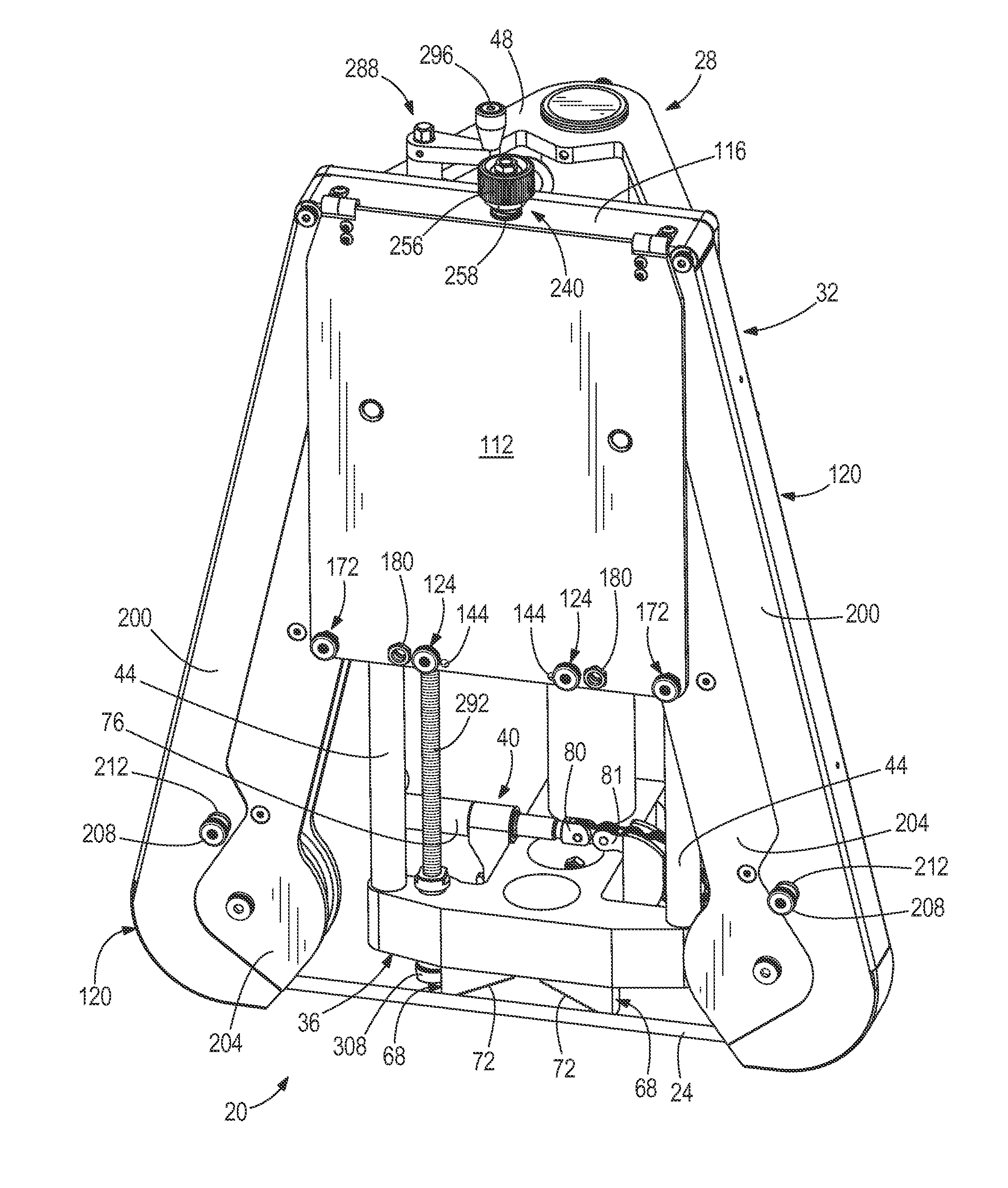
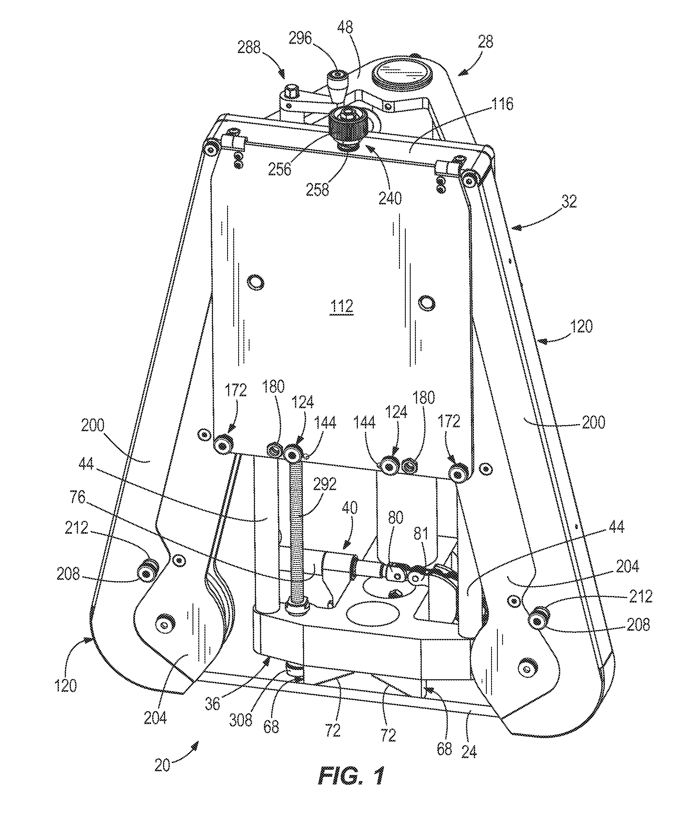
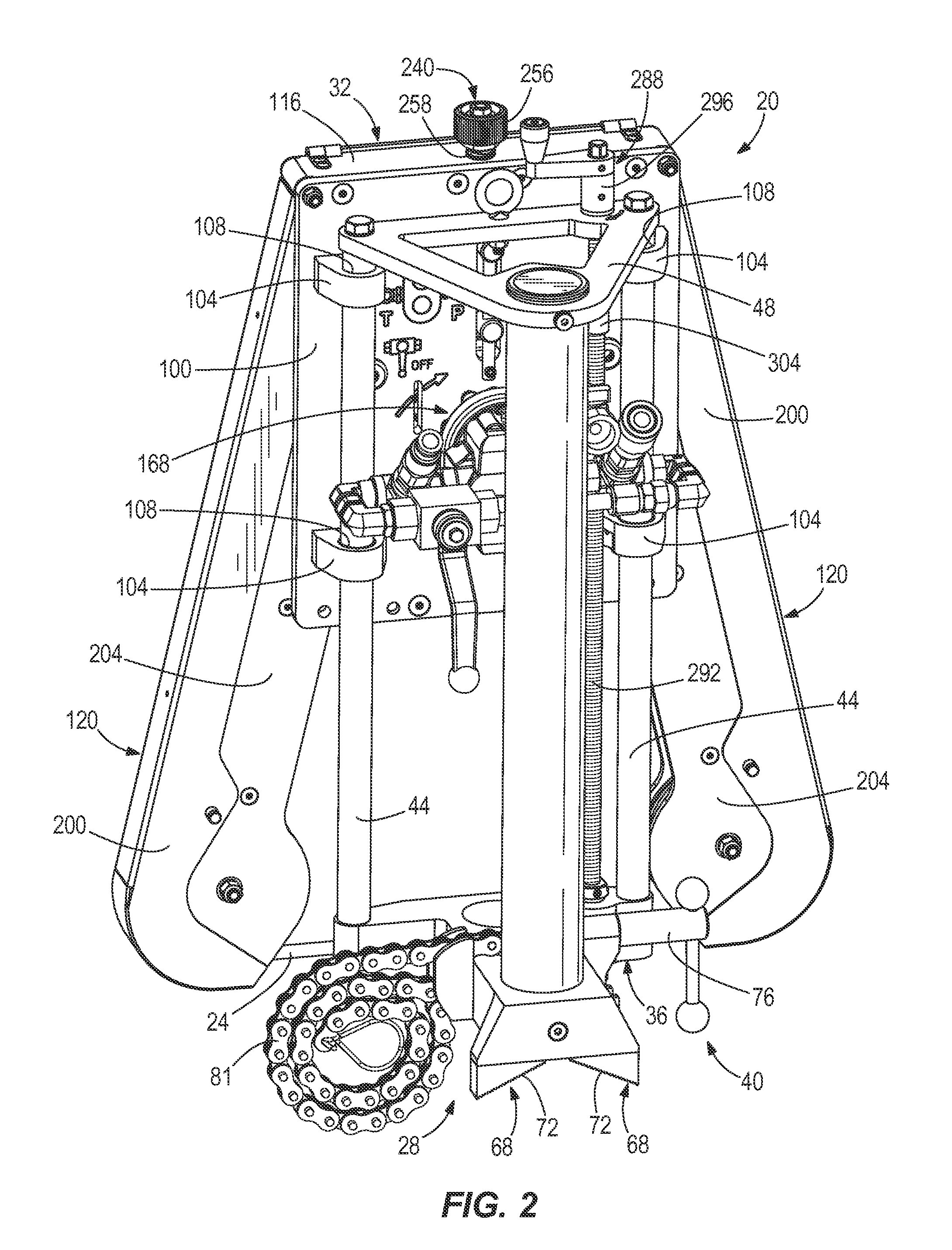
[0053]Referring to FIGS. 1-3, one example of a cutting apparatus 20 is shown. The cutting apparatus 20 may also be referred to as a wire saw. In this example, the cutting apparatus 20 is moveable between a first or operating position (see FIGS. 1 and 2) and a second, inoperable or storage position (see FIG. 3). When the cutting apparatus 20 is in the operating position, the cutting apparatus 20 is capable of cutting an object. The cutting apparatus 20 is adapted to cut a wide variety of objects. In one aspect, the cutting apparatus 20 is adapted to cut a cylindrical, hollow pipe. In such an example, the cutting apparatus 20 may cut a variety of different diameter pipes. For example, the cutting apparatus 20 may be able to cut a pipe having an outer diameter of up to about 9.6 inches.

[0054]In the storage position, the cutting apparatus 20 is very compact and can be introduced into a lot of small or tight environments that conventional cutting apparatuses or wires saws could not be in...


PUM

PropertyMeasurementUnit
depthaaaaaaaaaa
widthaaaaaaaaaa
depthaaaaaaaaaa

Abstract

A cutting apparatus includes a wire cutting member, a plurality of wheels about which the wire cutting member is at least partially wrapped, a first arm member supporting at least one of the plurality of wheels, and a second arm member supporting at least one of the plurality of wheels. The first arm member and the second arm member may be moveable between a first position, in which the cutting apparatus has a first size, and a second position, in which the cutting apparatus has a second size larger than the first size. A wire saw includes an adjustment member coupled to at least one of a plurality of wheels for moving the at least one of the plurality of wheels to adjust a tension of a wire cutting member. A wire saw includes a visual indicator for indicating an amount of tension applied to a wire cutting member

Description

RELATED APPLICATIONS[0001]The present application claims the priority benefit of U.S. Provisional Patent Application No. 61 / 889,624, filed Oct. 11, 2013, the content of which is incorporated by reference herein in its entirety.FIELD OF THE INVENTION[0002]The present disclosure generally relates to cutting apparatuses and, more particularly, to cutting apparatuses including wire cutting members for cutting objects such as pipes.BACKGROUND[0003]Cutting apparatuses including a wire for cutting products are generally referred to as wire saws. Wire saws are bulky items and may be unsafe to operate. The bulky wire saws are limited in the environments in which they may be operated and consume large spaces when not in use. Moreover, wire saws may not adequately couple to pipes or the operator may operate the wire saw in an unsafe position, thereby putting the operator in danger when operating the wire saws.SUMMARY[0004]The present disclosure is defined by the following claims, and nothing i...

Claims


Application Information

Patent Timeline
Patent Type & Authority Applications(United States)
IPC IPC(8): B23D57/00B26D1/48
CPCB23D57/0069B26D1/48B23D57/0092B23D57/0038B23D57/0061Y10T83/852Y10T83/9292
Inventor PIERCE, KENNETH R.GEARHART, MICHAEL W.COAKLEY, ROY C.
Owner ILLINOIS TOOL WORKS INC
Why Eureka
Try Eureka