Sensor device for an electrochemical energy store, electrochemical energy store, method for manufacturing a sensor device for an electrochemical energy store

a technology of electrochemical energy store and sensor device, which is applied in the direction of cell components, cell component details, instruments, etc., to achieve the effects of increasing reliability, preventing contact corrosion, and protecting the contact area

Active Publication Date: 2015-04-16
ROBERT BOSCH GMBH
View PDF25 Cites 3 Cited by
  • Summary
  • Abstract
  • Description
  • Claims
  • Application Information

AI Technical Summary

Benefits of technology

[0016]One advantage of the present invention is that the terminal contacts of the sensor device and the conductive contact points of the battery cell represent similar contact partners, so that formation of local elements or contact corrosion is avoided. Therefore, protection of the contacting areas from corrosion or formation of local elements is achieved by avoiding connections of dissimilar contact partners or in particular dissimilar metallic joining partners. In this case, the contacting areas or joints may be protected from exposure to corrosive media such as water, electrolytes, etc. Since an increased risk of corrosion exists due to the conductive electrolytes in the cell interior of the electrochemical energy store and the flow of even small electrical currents, for example, for measuring signals, the terminal contacts and also the sensor housing of the sensor device are designed for the purpose of withstanding corrosion or a chemical reaction. The contacting of the sensor device to the battery cell is conceived in such a way that no local elements may form due to the use of suitable material combinations or metal combinations for the contact partners and thus contact corrosion may be prevented. The use of such a sensor device in the cell interior of the electrochemical energy store may increase a reliability and lengthen the lifetime of the sensor device and in particular of the electrical contacting of the sensor device in relation to the electrochemical energy store.
[0017]According to one specific embodiment of the sensor device, the first terminal material on the surface of the first terminal contact may correspond to the second terminal material on the surface of the second terminal contact. In this case, therefore the at least one first contact material on the surface of the first contact point of the electrochemical energy store may correspond to the at least one second contact material on the surface of the second contact point of the electrochemical energy store. Such a specific embodiment offers the advantage that the electrical connection between the sensor device and the electrochemical energy store may be established in a simple and inexpensive way.
[0018]Alternatively, the first terminal material on the surface of the first terminal contact may differ from the second terminal material on the surface of the second terminal contact. In this case, therefore the at least one first contact material on the surface of the first contact point of the electrochemical energy store may differ from the at least one second contact material on the surface of the second contact point of the electrochemical energy store. Such a specific embodiment offers the advantage that the electrical connection between the sensor device and the electrochemical energy store may also be established in a reliable and corrosion-avoiding way in the case of contact points of the electrochemical energy store which have different compositions.
[0019]The first terminal contact may also have an exposed section of a carrier element of the sensor device. The first terminal material on the surface of the first terminal contact may correspond to a material of the carrier element. Additionally or alternatively, the second terminal contact may have an exposed section of the carrier element of the sensor device. The second terminal material on the surface of the second terminal contact may correspond to a material of the carrier element. The carrier element of the sensor device may have a so-called lead frame or the like. The carrier element may be formed, for example, from copper, aluminum, or the like. At least one section of the carrier element may be situated inside a sensor housing of the sensor device or may be housed with the aid of a sensor housing. The exposed sections of the carrier element may be situated outside a sensor housing of the sensor device. Such a specific embodiment offers the advantage that the electrical connection between the sensor device and the electrochemical energy store may be established in a simple and inexpensive way using a carrier element which is installed anyway.
[0020]Furthermore, the first terminal contact may have a section of a carrier element of the sensor device and a first coating layer. The first terminal material on the surface of the first terminal contact may correspond to a material of the first coating layer. Additionally or alternatively, the second terminal contact may have a section of the carrier element of the sensor device and a second coating layer. The second terminal material on the surface of the second terminal contact may correspond to a material of the second coating layer. The coating layers may be applied to sections of the carrier element situated outside the sensor housing. The coating layers may be formed, for example, from silver, copper, aluminum, or the like. Such a specific embodiment offers the advantage that the electrical connection between the sensor device and the electrochemical energy store may also be established in a simple, reliable, and corrosion-avoiding way with the aid of at least one of the coating layers in the case of contact points, which have differing compositions, of the electrochemical energy store.
[0021]According to one specific embodiment of the electrochemical energy store, the electrochemical energy store may have a first electrode assembly having a first current conductor and a second electrode assembly having a second current conductor.

Problems solved by technology

One challenge in this case is in particular an effective battery management system, which may monitor the function of individual cells of the battery and control their charging operation.

Method used


Image

  • Sensor device for an electrochemical energy store, electrochemical energy store, method for manufacturing a sensor device for an electrochemical energy store
  • Sensor device for an electrochemical energy store, electrochemical energy store, method for manufacturing a sensor device for an electrochemical energy store
  • Sensor device for an electrochemical energy store, electrochemical energy store, method for manufacturing a sensor device for an electrochemical energy store

Examples


Embodiment Construction

[0030]In the following description of preferred exemplary embodiments of the present invention, identical or similar reference numerals are used for the elements which are shown in the various figures and act similarly, a repeated description of these elements being omitted.

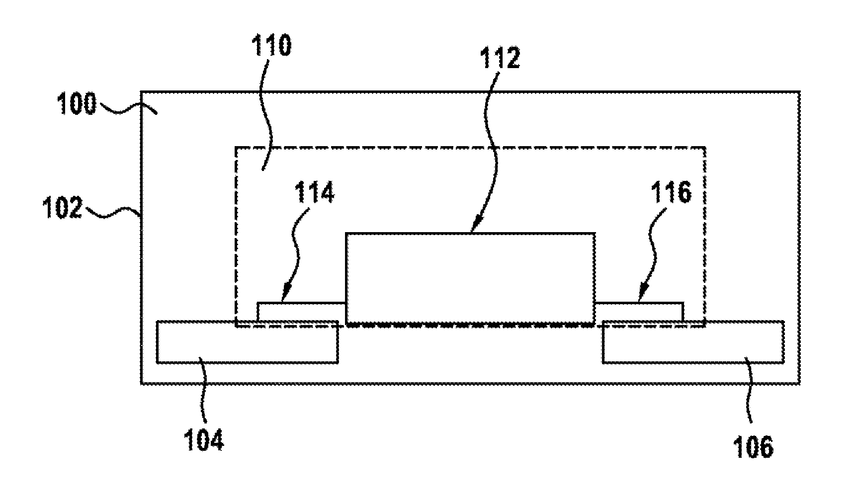
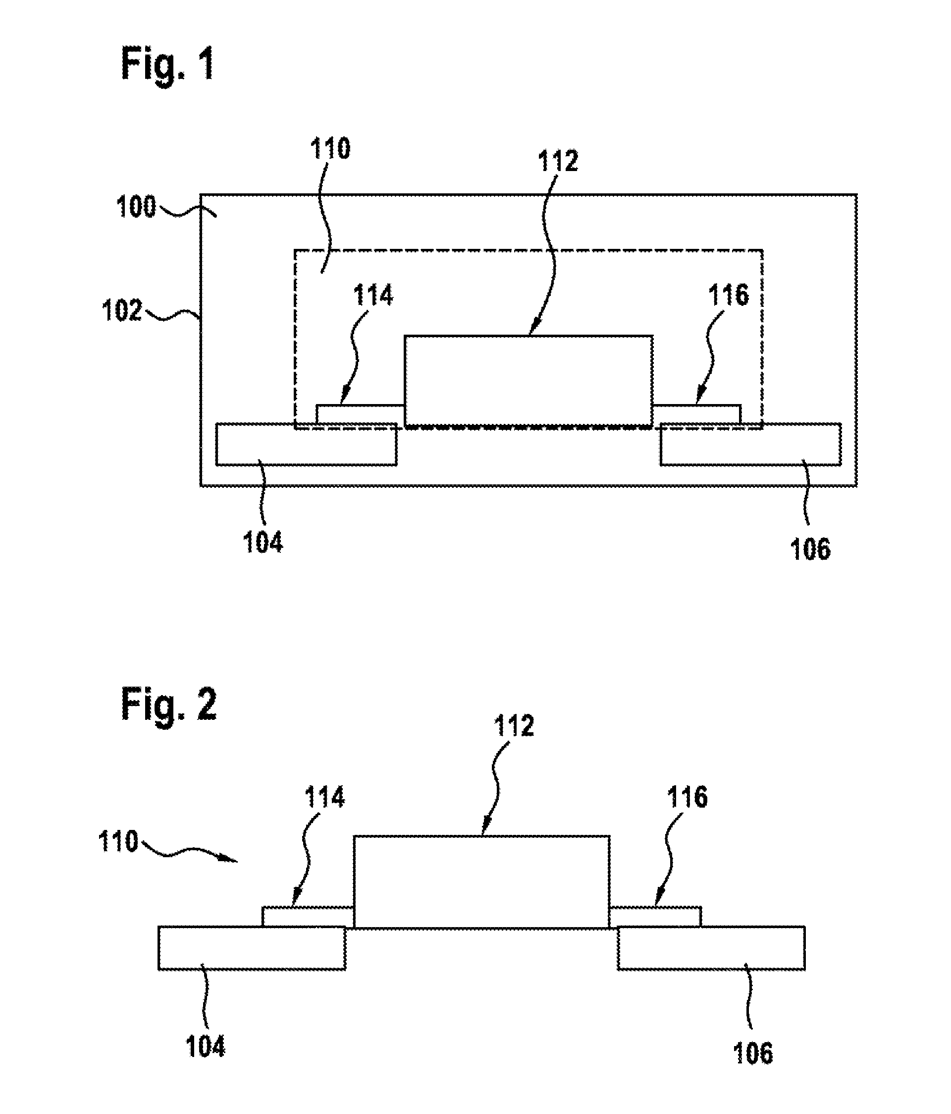
[0031]FIG. 1 shows a schematic view of an electrochemical energy store 100 according to one exemplary embodiment of the present invention. Electrochemical energy store 100, a housing 102, a first contact point 104 or first contact surface, a second contact point 106 or second contact surface, a sensor device 110, a sensor housing 112, a first terminal contact 114, and a second terminal contact 116 are shown. Electrochemical energy store 100 may be a lithium-ion cell, for example.

[0032]Electrochemical energy store 100 has housing 102, first contact point 104, and second contact point 106. First contact point 104 and second contact point 106 are situated inside housing 102. Electrochemical energy store 100 furtherm...


PUM

PropertyMeasurementUnit
electrically conductiveaaaaaaaaaa
electrically conductivelyaaaaaaaaaa
electrochemicalaaaaaaaaaa

Abstract

A sensor device for contacting first and second contact points of an electrochemical energy store which are situated inside a housing of the electrochemical energy store includes: a first terminal contact for the electrically conductive connection of the sensor device to the first contact point, a first terminal material on a surface of the first terminal contact corresponding to at least a first contact material on a surface of the first contact point; and a second terminal contact for the electrically conductive connection of the sensor device to the second contact point, a second terminal material on a surface of the second terminal contact corresponding to at least a second contact material on a surface of the second contact point.

Description

BACKGROUND OF THE INVENTION[0001]1. Field of the Invention[0002]The present invention relates to a sensor device for an electrochemical energy store, an electrochemical energy store, a method for manufacturing a sensor device for an electrochemical energy store, and a method for electrically contacting a sensor device of an electrochemical energy store.[0003]2. Description of the Related Art[0004]With ever-growing demand for alternative drive concepts, for example, in particular electric drives are entering the focus of consideration. In the automobile industry, for example, battery packets which are used generally include multiple modules, which may in turn be assembled from multiple lithium-ion cells, for example. One challenge in this case is in particular an effective battery management system, which may monitor the function of individual cells of the battery and control their charging operation. Furthermore, for example, defective cells may be shut down and / or bypassed and stat...

Claims


Application Information

Patent Timeline
Patent Type & Authority Applications(United States)
IPC IPC(8): G01R31/36H01R43/16H01M50/569
CPCG01R31/3644G01R31/3627H01R43/16H01M10/48H01M10/486H01M50/569Y10T29/49117Y10T29/49204Y02E60/10G01R31/385
Inventor HENRICI, FABIANBRUENDEL, MATHIASGRIMMINGER, JENS
Owner ROBERT BOSCH GMBH
Why Eureka
Try Eureka