Image display device, presentation box employing same, and method of driving image display device

Active Publication Date: 2015-04-16
SHARP KK
View PDF5 Cites 12 Cited by
  • Summary
  • Abstract
  • Description
  • Claims
  • Application Information

AI Technical Summary

Benefits of technology

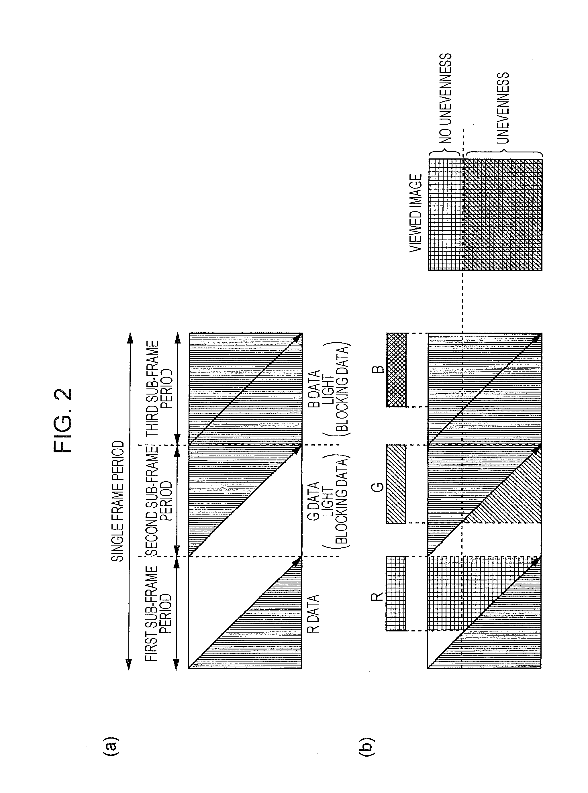
[0036]According to the first aspect of the invention, the control is performed on the light source lighting time period of the illumination unit and at least one of the lighting start time of the illumination unit and the start time of the scanning operation such that the single or multiple color light of the backlight corresponding to the single or multiple color data is emitted, for each of periods corresponding to periods, in which only the single or multiple color data necessary for display of the image with the desired color is supplied, in the sub-frame periods. Thereby, it is possible to set the display area, which is for displaying the image with the desired color in which occurrence of color unevenness is suppressed, at an arbitrary position on the display panel. Further, in the period in which the same color light of the backlight is emitted, the number of the scanning operations performed is only one. Therefore, it is possible to reduce the load on the driving circuit, and it is possible to secure the time period necessary for the single or multiple color data to be supplied.
[0037]According to the second aspect of the invention, the single or multiple color data supplied to the non-display area for each sub-frame period is the same data. Hence, in the non-display area, occurrence of color unevenness is suppressed.
[0038]According to the third aspect of the invention, by performing the scanning operation earlier or later than the start time of the sub-frame period, it is possible to widen the display area capable of displaying the image in which occurrence of color unevenness is suppressed, and it is possible to increase the luminance of the image in which occurrence of color unevenness is suppressed.
[0039]According to the fourth aspect of the invention, when t

Problems solved by technology

Thereby, light blocking data is supplied to all the pixels, and thus t

Method used


Image

  • Image display device, presentation box employing same, and method of driving image display device
  • Image display device, presentation box employing same, and method of driving image display device
  • Image display device, presentation box employing same, and method of driving image display device

Examples


first embodiment

2. First Embodiment

[0132]A liquid crystal display device according to the first embodiment of the present invention is a liquid crystal display device configured by hardware.

2.1 Configuration of Liquid Crystal Display Device

[0133]FIG. 9 is a block diagram illustrating a configuration of a liquid crystal display device according to the first embodiment of the present invention. As illustrated in FIG. 9, the liquid crystal display device includes an image control circuit 10, a display element driving circuit 40, a light source driving circuit 50, a liquid crystal panel 60, and a backlight unit 70. When an input signal including the image data is supplied from the outside to the image control circuit 10, the image control circuit 10 generates, on the basis of the input signal, the data for image display, a timing control signal for controlling the light source lighting start time, the light source lighting time period, and the light source luminance data. The data for image display is ...

second embodiment

3. Second Embodiment

3.1 Configuration of Liquid Crystal Display Device

[0192]FIG. 19 is a block diagram illustrating a configuration of a liquid crystal display device according to a second embodiment of the present invention. As illustrated in FIG. 19, the configuration of the liquid crystal display device is the same as the configuration of the liquid crystal display device illustrated in FIG. 1. Accordingly, in FIG. 19, elements the same as the elements of the liquid crystal display device illustrated in FIG. 1 are represented by the same reference numerals and signs, a description thereof will be omitted, and different elements will be described.

[0193]An image control circuit 80 illustrated in FIG. 19 includes an arithmetic circuit 81 which is formed of a CPU, a RAM, and the like. When the input signal is supplied from the outside, on the basis of the input signal, in accordance with the flowchart to be described later, the image control circuit 80 generates the light source lumi...

modification example

3.4 Modification Example

[0213]FIG. 24 is a block diagram illustrating a configuration of a liquid crystal display device according to a modification example of the second embodiment of the present invention. As illustrated in FIG. 24, the configuration of the liquid crystal display device is the same as the configuration of the liquid crystal display device illustrated in FIG. 1. Accordingly, in FIG. 24, elements the same as the elements of the liquid crystal display device illustrated in FIG. 1 are represented by the same reference numerals and signs, a description thereof will be omitted, and different elements will be described.

[0214]An image control circuit 85 included in the liquid crystal display device illustrated in FIG. 24 includes the arithmetic circuit 81 which is formed of a CPU, a RAM, and the like, and a memory 86 which is connected to the arithmetic circuit 81. When the input signal is supplied from the outside, on the basis of the input signal, the image control circ...


PUM


Abstract

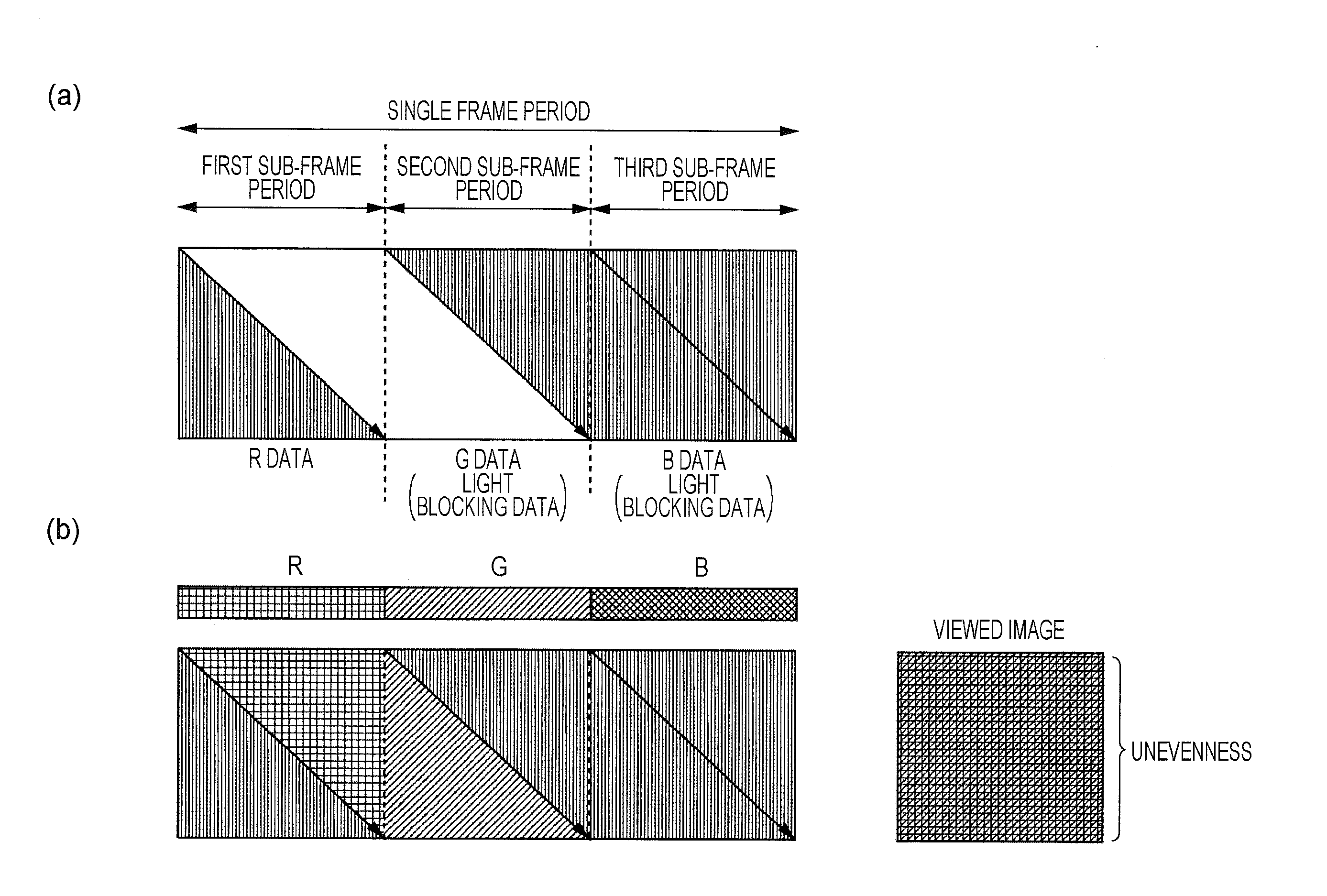
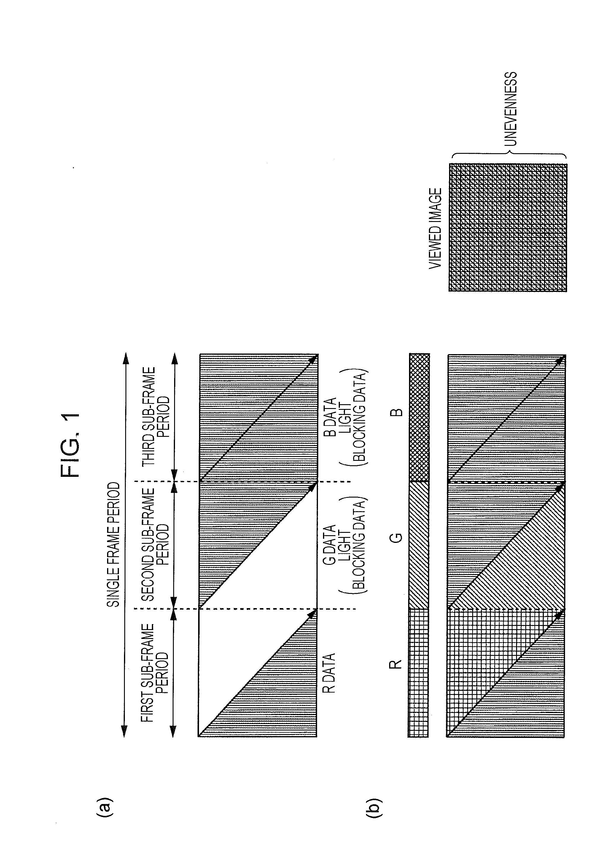
An image display device is capable of displaying an image, in which occurrence of color unevenness is suppressed. A method of driving the image display device is also disclosed. In an area above the dotted line, red light is transmitted in a first sub-frame period. In second and third sub-frame periods, light blocking data are respectively supplied as green data and blue data. Therefore, green light and blue light cannot be transmitted through the area. Hence, a red image with no color unevenness is displayed in the area. In contrast, in an area under the dotted line, the red light is transmitted in the first sub-frame period, and the green light is transmitted in the second sub-frame period. As a result, in a viewed image of the area, there is color unevenness where green is mixed to red.

Description

TECHNICAL FIELD[0001]The present invention relates to an image display device, a presentation box employing the same, and a method of driving the image display device. More specifically, the present invention relates to an image display device that is driven using a field sequential system, a presentation box employing the same, and a method of driving the image display device.BACKGROUND ART[0002]In recent years, the field sequential system as one of driving systems of a liquid crystal, display device, which displays a color image, has been developed. In the field sequential system, by sequentially switching light emitting elements such as cathode fluorescent lamps (CCFL) and light emitting diodes (LED) of red (R) light, green (G) light, and blue (B) light as light of a backlight and by sequentially supplying color data corresponding to colors of light of the respective light emitting elements to a liquid crystal panel in synchronization with the switching, transmission states there...

Claims


Application Information

Patent Timeline
IPC IPC(8): G09G3/36
CPCG09G3/3607G09G3/3677G09G2310/08G09G2320/0233G09G2320/0242G09G2380/00G09G2310/0235G09G3/3413G09G3/346G09G3/3648G09G2310/024G09G2320/0646G09G3/3426
Inventor KOBAYASHI, MASAMITSU
Owner SHARP KK
Why Eureka
Try Eureka