Molding device

Active Publication Date: 2015-04-16
AIRBUS HELICOPTERS DEUT GMBH
View PDF3 Cites 4 Cited by
  • Summary
  • Abstract
  • Description
  • Claims
  • Application Information

AI Technical Summary

Benefits of technology

[0021]According to a further preferred embodiment of the invention a contact force generating element is provided between the heat exchangers, said contact force generating

Problems solved by technology

When a thermal capacity is large of a molding die that is used for molding, it takes time for the heat to transfer from a heat source to a pressing surface contacting a product to be molded.
Oil as heat transf

Method used


Image

  • Molding device
  • Molding device
  • Molding device

Examples


Example

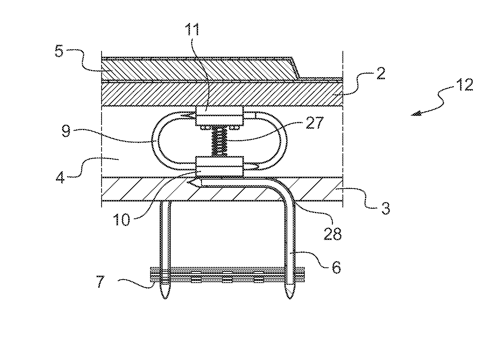
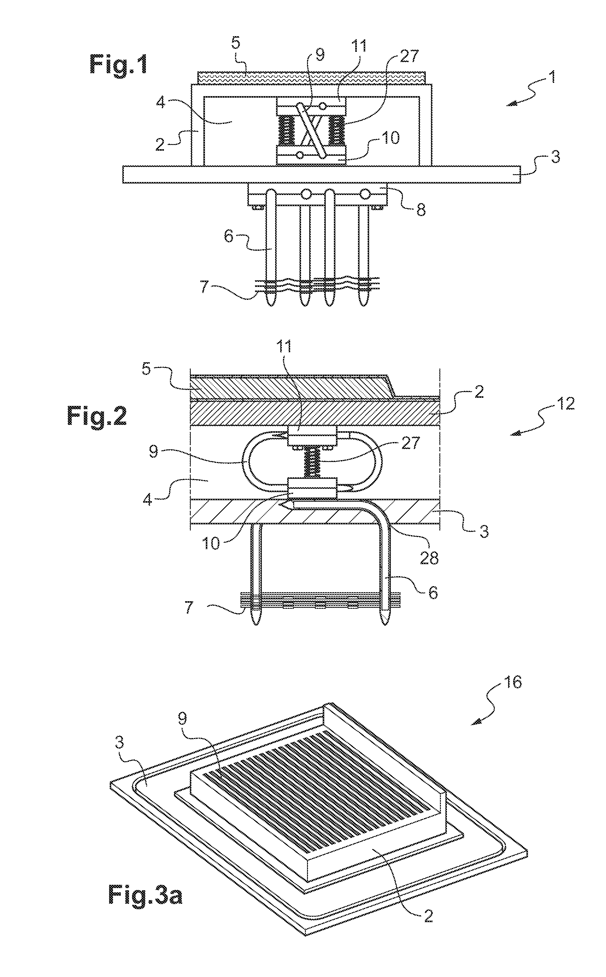
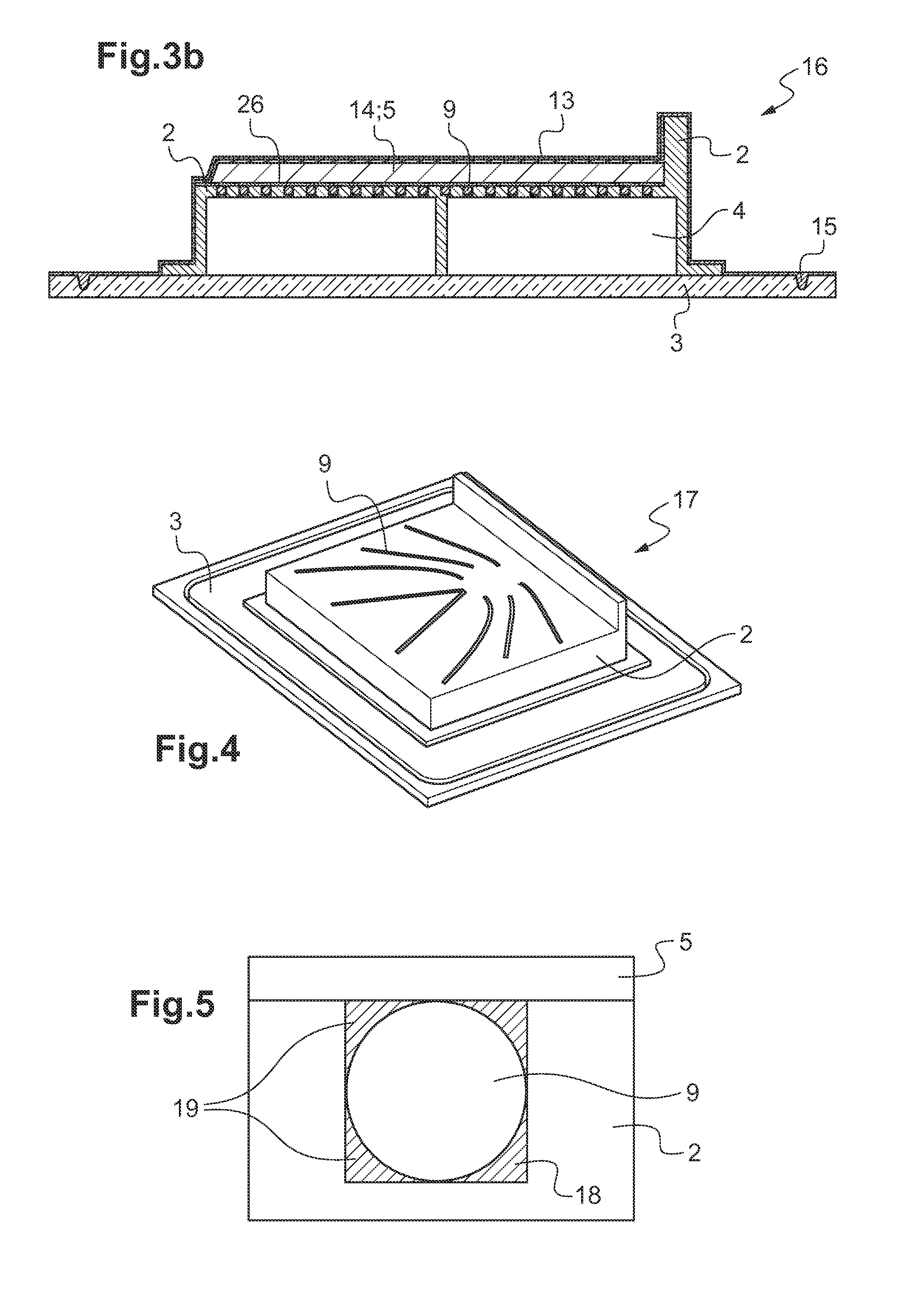
[0033]According to FIG. 1 a retrofitting molding device 1 comprises a molding die 2 with a base plate 3 and a vacuum chamber 4 within the molding die 2 and the base plate 3. The composite material 5 to be cured is on the molding die 2.

[0034]An outer heat pipe 6 is provided with fins 7 as multi-layered heat exchanger at a free end of the outer heat pipe 6 and with a two-dimensional heat exchanger 8. The two-dimensional heat exchanger 8 of the outer heat pipe 6 is in planar contact for heat exchange to the base plate 3 of the molding die 2. The fins 7 of the multi-layered heat exchanger are adapted to supply heat into the outer heat pipe 6 while the two-dimensional heat exchanger 8 is adapted to supply the heat from the fins 7 into the base plate 3.

[0035]An inner heat pipe 9 is provided with a two-dimensional base heat exchanger 10 and a two-dimensional die heat exchanger 11. The two-dimensional base heat exchanger 10 is in planar contact for heat exchange with the base plate 3 and th...


PUM

PropertyMeasurementUnit
Forceaaaaaaaaaa
Thermal conductivityaaaaaaaaaa

Abstract

A molding device for curing of composite components comprising: a molding die, composite material in the molding die, heat application means, sheathing means for the composite material and the molding die and vacuum means for the application of vacuum to the composite material in the molding die. The heat application means comprise at least one heat pipe with a heat exchanger attached to the molding die for thermal conduction to the composite material.

Description

CROSS REFERENCE TO RELATED APPLICATION[0001]This application claims priority to European patent application No. 13 400022.3 filed on Oct. 15, 2013, the disclosure of which is incorporated in its entirety by reference herein.BACKGROUND OF THE INVENTION[0002](1) Field of the Invention[0003]The invention is related to a molding device for composite components with the features of the preamble of claim 1.[0004](2) Description of Related Art[0005]Molding of composite components in molding dies needs typically 180° C. for curing. When a thermal capacity is large of a molding die that is used for molding, it takes time for the heat to transfer from a heat source to a pressing surface contacting a product to be molded. Oil as heat transfer medium is incompatible with composite components and thus disadvantageous for the molding of composite components. Standard heat pipes provide heat at a temperature range from −20° C. to 230° C. depending from used internal medium. Standard heat pipes pro...

Claims


Application Information

Patent Timeline
IPC IPC(8): B29C35/00B29C70/54B29C35/04B29C70/44
CPCB29C35/007B29C70/443B29C70/54B29C35/041B29C33/02B29C70/44
Inventor HERTLE, THOMASARENT, JAN-CHRISTOPHLOY, CHRISTOPH
Owner AIRBUS HELICOPTERS DEUT GMBH
Why Eureka
Try Eureka