Resisting system for making variable mechanical resistance exercises

a mechanical resistance and resistance system technology, applied in the field of resistance systems for making variable mechanical resistance exercises, can solve the problems of user exhaustion, exercise apparatuses that do not allow the user to preform, and no exercise apparatuses known which allow the user to use a variety of commands using brain and/or brain waves, so as to improve the accuracy and precision of mechanical resistance (weight) and increase the amount of exercises. , the effect of improving performance results

Active Publication Date: 2015-04-16
BISSU MOISES BUCAY
View PDF3 Cites 39 Cited by
  • Summary
  • Abstract
  • Description
  • Claims
  • Application Information

AI Technical Summary

Benefits of technology

[0013]Another advantage of the present invention over the U.S. Pat. No. 7,572,213 and U.S. Pat. No. 7,413,534 is the piston rearrangement. In such patents, the piston is located in the carriage which connects at the same time with the arms of the system. This vertically limits the positioning of such arms and of their rotation, point, as the lower vertical limit for displacing the arms is the stop that exists between the piston rod and the base or the system floor. With the relocation of the piston, a lower limit, which is much lower than the piston rod stop and the system base do not exist. This fact allows an increase in the amount of exercises that a user can perform, because the relation between the rotation point of the arms and the body of the user allows the user to execute the exercise appropriately.
[0014]Furthermore, and, in contrast with the previous patent systems, U.S. Pat. No. 7,572,213 and U.S. Pat. No. 7,413,534, the present invention makes it easier, in mechanical terms, for an improved precision and accuracy in the mechanical resistance (weight) that a user experiences. Because of the mechanical disposition of the elements thereof where, a linear relation between the variation of the weight that the user experiences and the number of strains contained in a guide screw, improved performance results will be explained in greater detail in the description that follows.
[0015]Likewise, and, in contrast with the previous patent systems, U.S. Pat. No. 7,572,213 and U.S. Pat. No. 7,413,534, the present invention, by providing the previous linear relation described between the weight variation experienced by the user and the number of strains contained in the guide screw, it makes it easier to obtain the engineering calculation for optimizing the system. As in U.S. Pat. No. 7,572,213 and U.S. Pat. No. 7,413,534, the algorithm used for calculating the weight variation experienced by the user is very complex due to the mechanical and thermodynamic factors found in such systems. Therefore the present invention solves the previous problem by providing a mechanical disposition in which the mechanical resistance (weight) experienced by the user is linear in relation to one mechanical factor.

Problems solved by technology

The problem with any conventional machine, which cannot offer the user different weights in each part of the repetition, is that it causes the user to reach up to a point of muscular exhaustion when he or she cannot move the weight at the positive part, even when he or she had the extra strength for continuing at the negative part.
However, the majority of the exercise apparatuses do not allow the user to preform exercises with variable resistance with precise and immediate changes in the resistance during the execution of the exercise.
Furthermore, there are no exercise apparatuses known which allow the user to use a variety of commands using brain and / or brain waves, or with respect to any body movement detected by the electronic devices, for changing the resistance found during an exercise.
However, the main problem with the system of U.S. Pat. No. 7,572,213 and U.S. Pat. No. 7,413,534 and with any other type of pneumatic or hydraulic machines, is that every time the user requires more mechanical (weight) resistance for executing exercise, the piston employed needs to take air from the pressurized air storage tank, or when the user requires a weight reduction, the system has to release air to the environments which creates an enormous waste of air.
Furthermore, in case of emergency, there is an air waste in the pervious systems, which results in energy waste, which is used for powering the compressor used to load air to the system.
Another drawback of the inventions described in previous patents, U.S. Pat. No. 7,572,213 and U.S. Pat. No. 7,413,534, is that in case of emergency, when performing the emergency command in any of the embodiments, such as when the body remains still in a certain position for a fraction of time, the air takes some seconds to exit.
This is very undesirable.
As in U.S. Pat. No. 7,572,213 and U.S. Pat. No. 7,413,534, the algorithm used for calculating the weight variation experienced by the user is very complex due to the mechanical and thermodynamic factors found in such systems.
On the other hand, in prior art systems, there is the spatial limit for increasing the maximum weight of an exercise apparatus for increasing the number of weight plates and discs.
If the user wished to exercise with a weight of 300 kg, this would require the equipment to be disassembled for changing the plates to 15 or 20 kg each, which would be very complicated.
Furthermore, there are also presently individual machines of integrated weight (with plates), for example the “X-force” machine, which suffers from the technical problem of waiting a specific time for the weight change to be made.
Another disadvantage is that the weight limit, either lower or higher, is that contained in the machine from the manufacture, i.e., the plates set.
These machines do not make an immediate weight change as the fluids take time to pass from one side to the other and, their solid weight versions (which are still in development), are limited in that the maximum weight for the user is the weight already in the machine.

Method used


Image

  • Resisting system for making variable mechanical resistance exercises
  • Resisting system for making variable mechanical resistance exercises
  • Resisting system for making variable mechanical resistance exercises

Examples


Embodiment Construction

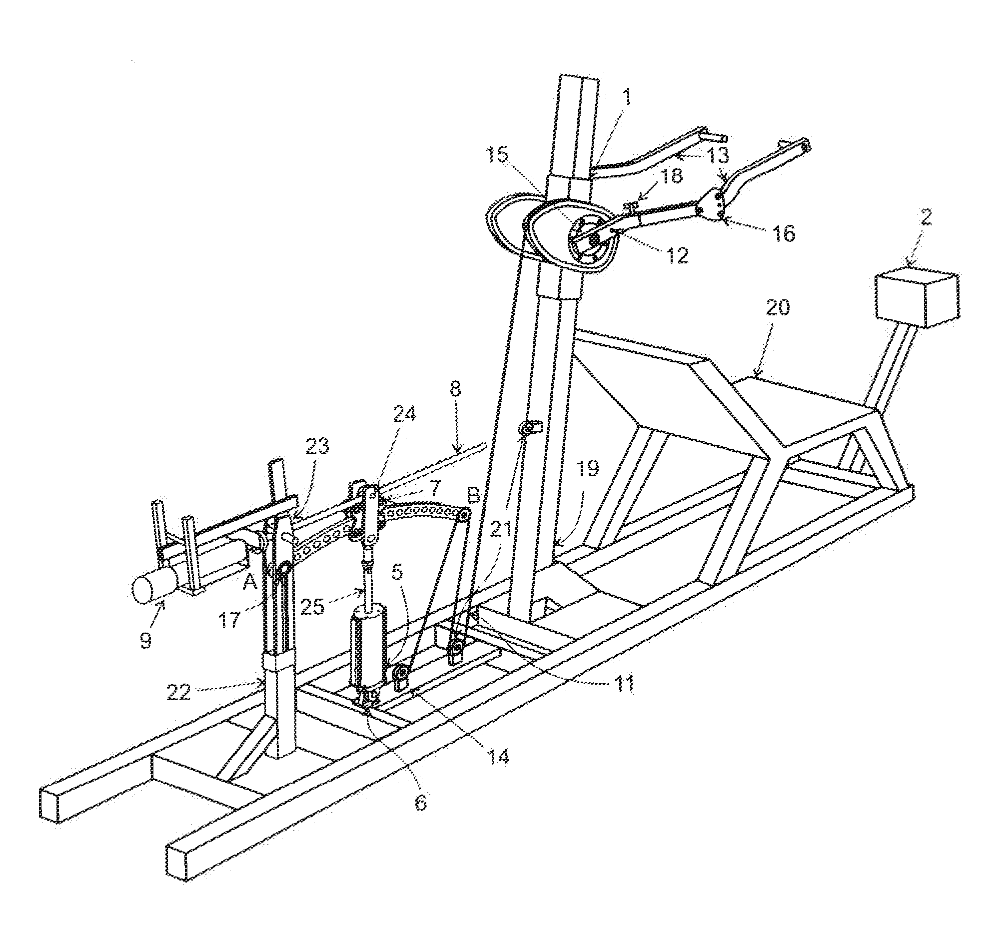
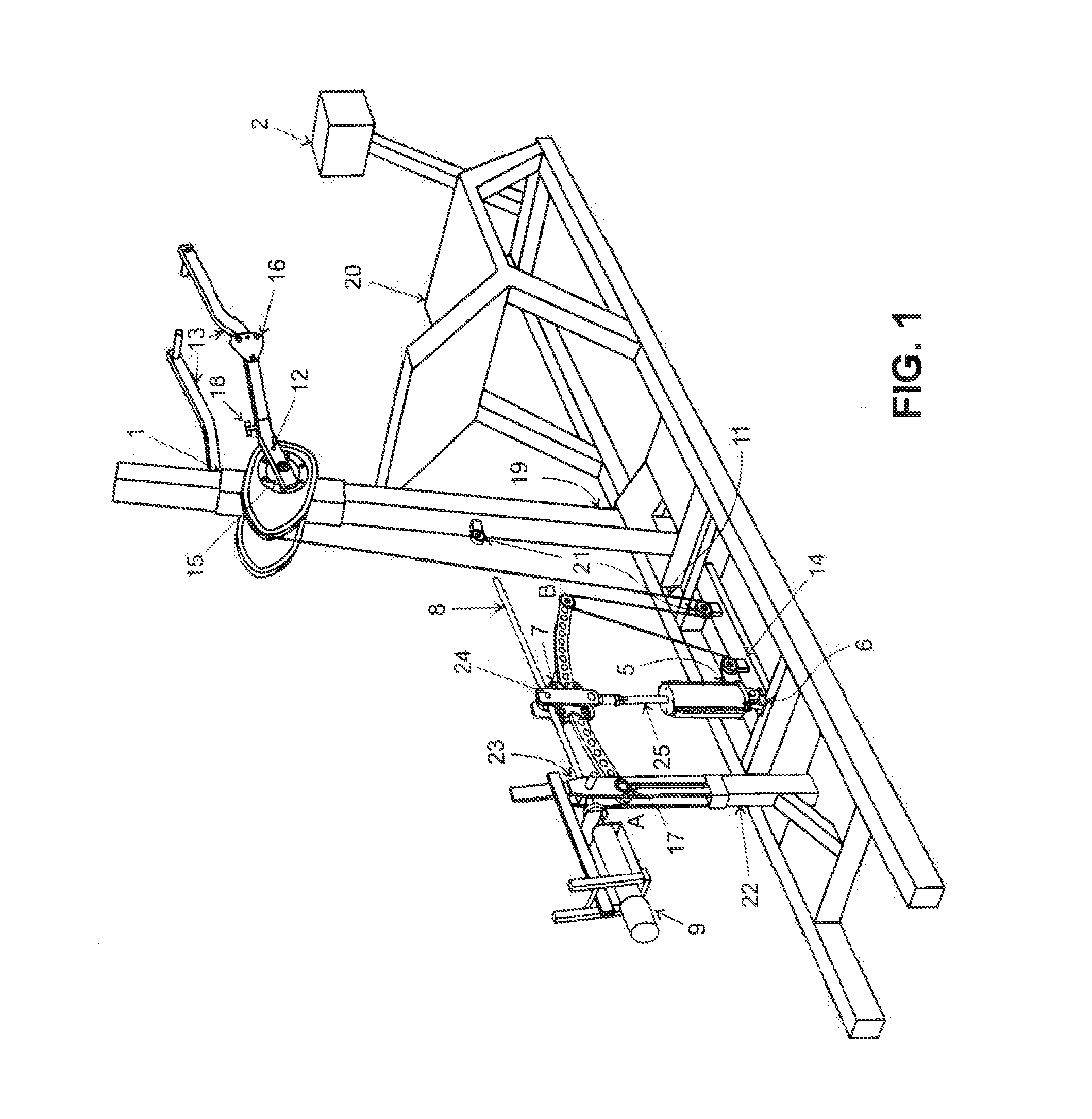
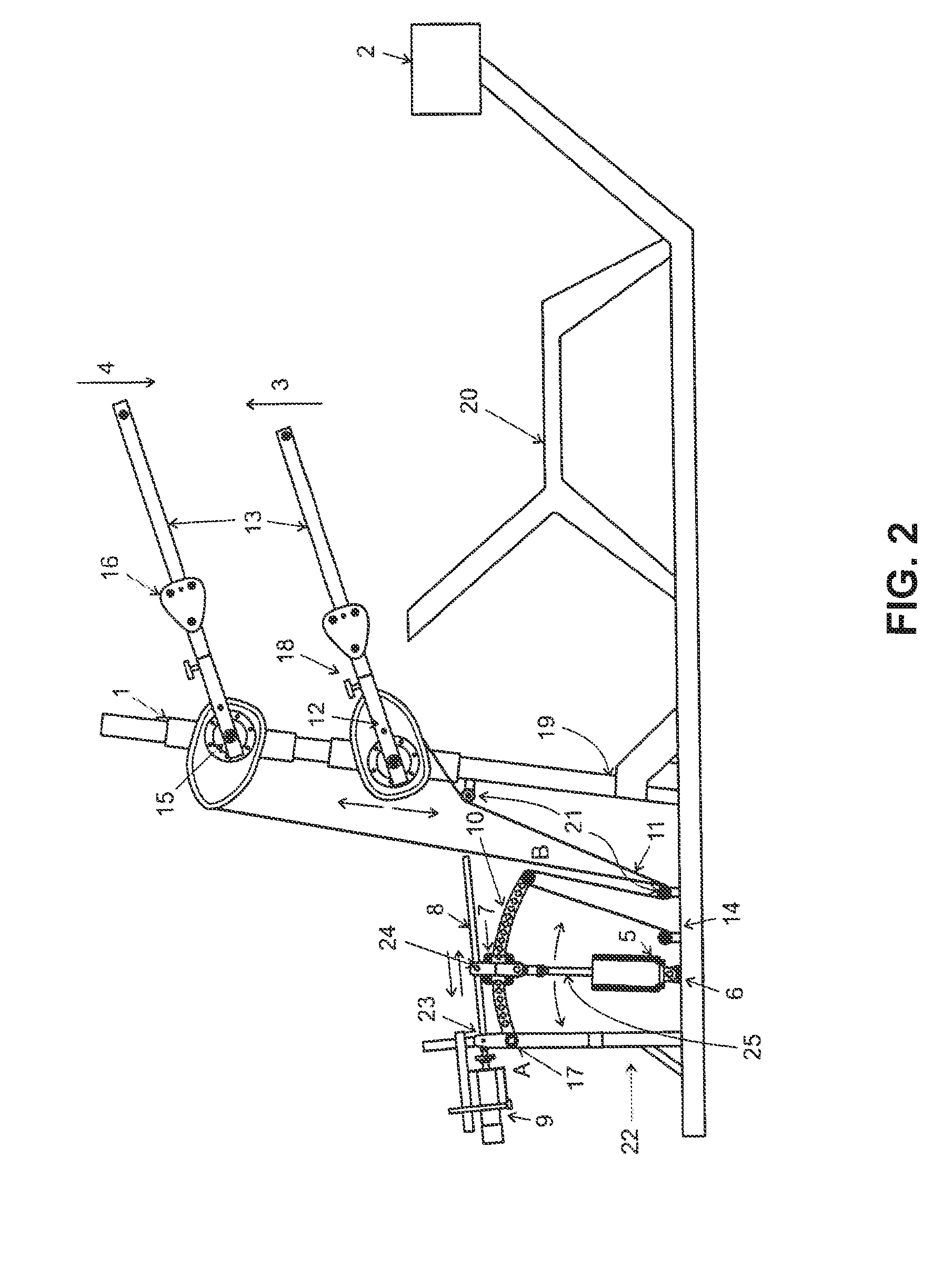
[0047]In a preferred embodiment of the present invention, a mechanical resisting system (weight), consisting of a pneumatic piston, (5) is provided. This piston pivots in its base (6), and the end of its piston rod is connected to a carriage (7) which in turn is connected to a guide screw (8), which is connected to a motor (9), which causes the carriage (7) travel along a cam arm (10) having a pivot point (17). At its free end (B), the cam arm (10) is connected, by a traction element (cable) (11) to the irregular pulley (12), which, in turn, is attached to the arms of the machine (13), and both (arm and pulley) rotate about the axis (15). When moving away the carriage (7) from cam arm pivot (A), “the lever arm” becomes smaller, offering more resistance (weight) to the user and vice versa.

[0048]In order to move the carriage (1) which encloses the irregular pulley (12) and arms (13) along the column (19), a system with a retractable cartridge with clutch (14) was designed, it allows f...


PUM


Abstract

The present invention relates to equipment, apparatus and systems used for exercising muscle groups of the body, more specifically, a resistance system for making variable mechanical resistance exercises, which receive voice commands, changes in brain waves and/or any body movement.

Description

FIELD OF THE INVENTION[0001]The present invention relates to apparatuses and systems used for exercising the body. In particular, the invention relates to a variable (weight) mechanical resistance system with pneumatic, mechanical and / or pulley elements for applying to exercising machines. Furthermore, the invention refers to a system for exercise, which allows modulating the mechanical resistance thereof by means of voice commands, brain waves and / or body movements.BACKGROUND OF THE INVENTION[0002]Over time, resistance machines for use during exercise have been developed in which the weight can be dynamically modified, i.e., during the execution thereof.[0003]One of the goals is being able to optimize each repetition by giving the user more weight at the negative part of the repetition, than at the positive part thereof.[0004]Naturally, everybody has more strength in the negative part than in the positive part.[0005]For example, in the case of a sit-up exercise, the negative part i...

Claims


Application Information

Patent Timeline
Patent Type & Authority Applications(United States)
IPC IPC(8): A63B21/062
CPCA63B21/062A63B21/00072A63B21/00076A63B21/0083A63B21/0087A63B21/023A63B21/06A63B21/155A63B21/159A63B21/4035A63B23/0211A63B23/03525A63B23/1209A63B23/1218A63B23/1227A63B24/0087A63B2024/0093A63B2071/0675A63B2071/0677A63B2071/068A63B2071/0683A63B2220/13A63B2220/16A63B2220/803A63B2220/805A63B2225/50A63B2230/105
Inventor BISSU, MOISES BUCAY
Owner BISSU MOISES BUCAY
Why Eureka
Try Eureka