
Pump having wear and wear rate detection

a technology of wear and wear rate detection and pump, which is applied in the direction of positive displacement liquid engine, machine/engine, instruments, etc., can solve the problems of preventing the pump from producing adequate pressure, dispensing grease, and adding additives that wear the pistons of the pump

Active Publication Date: 2015-04-23
LINCOLN INDUSTRIES CORP
View PDF0 Cites 5 Cited by
  • Summary
  • Abstract
  • Description
  • Claims
  • Application Information

AI Technical Summary

Benefits of technology

The invention has several benefits and can lead to improved performance.

Problems solved by technology

Although these additives reduce bearing wear, they act as an abrasive in lubrication pumps.
In particular, the additives wear the pistons in the pumps during repetitive back and forth pumping action under high pump pressures.
Piston wear can prevent pumps from producing adequate pressures and dispensing grease.

Method used

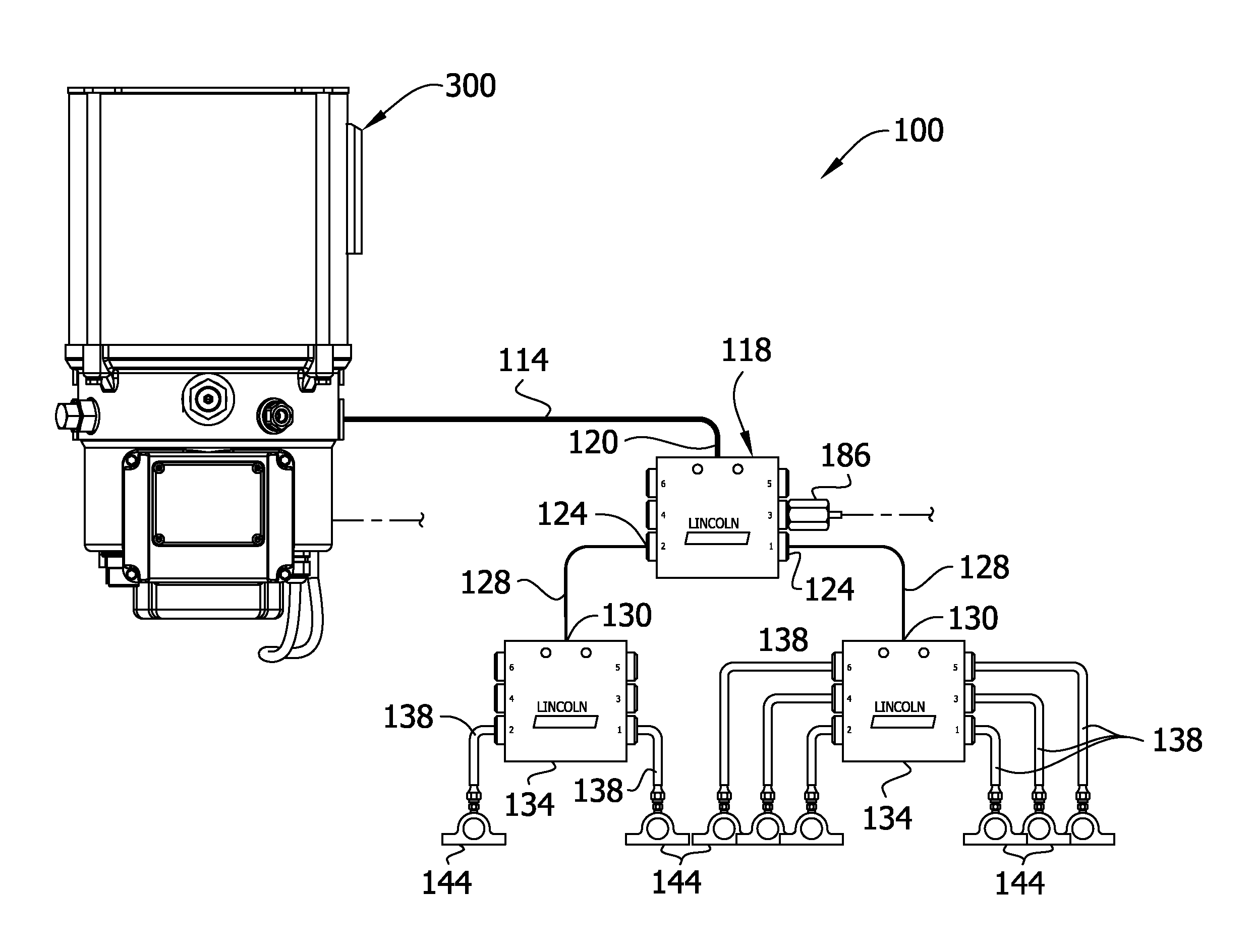
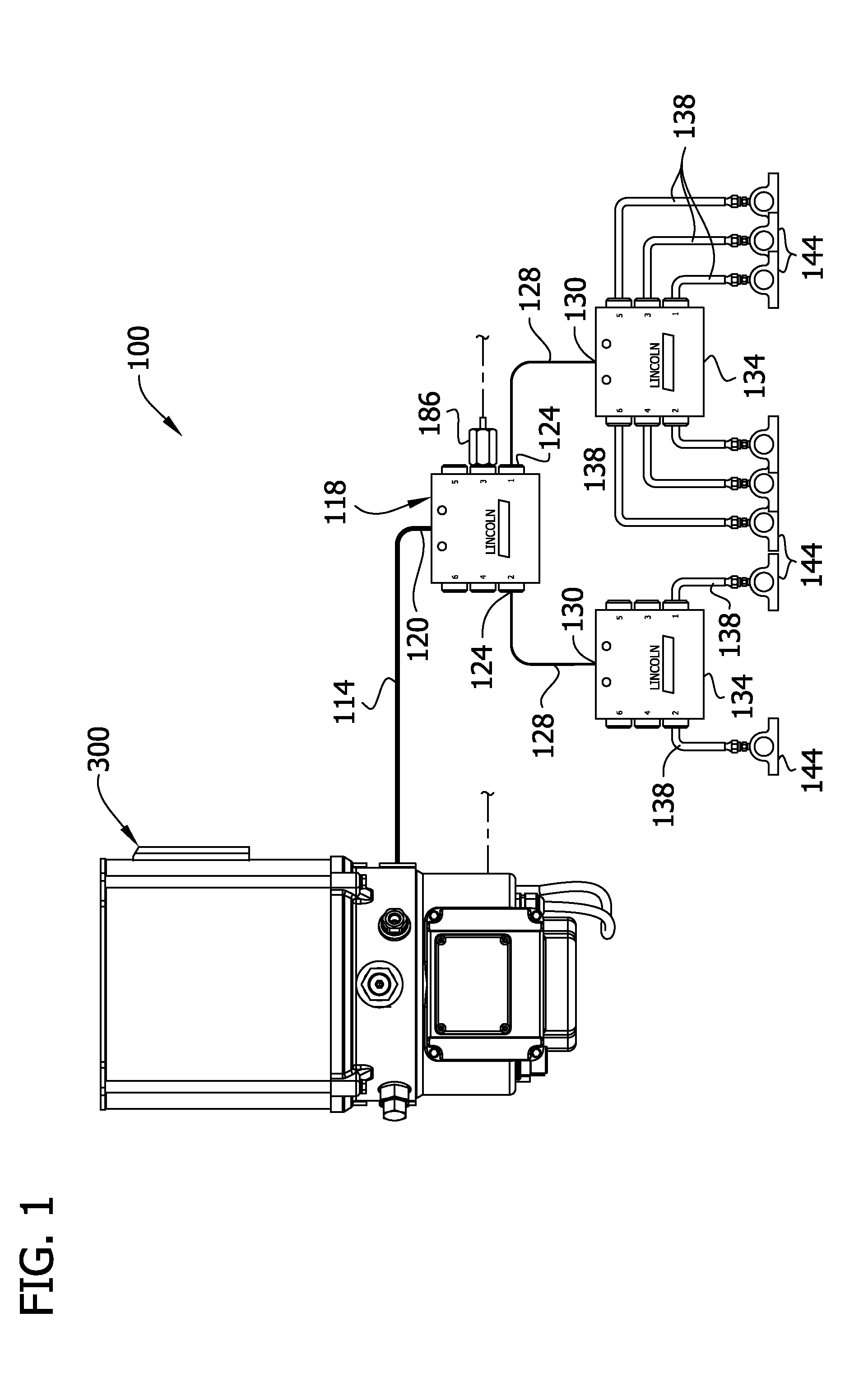
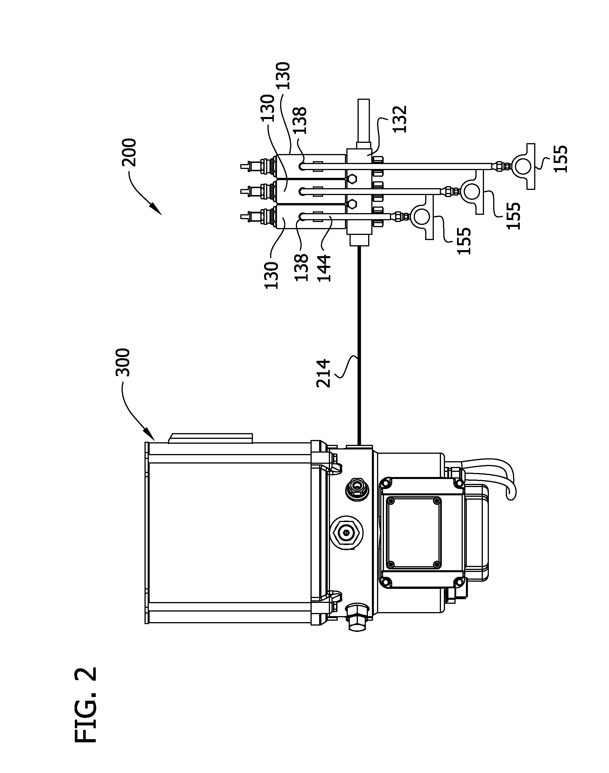

Image

  • Pump having wear and wear rate detection
  • Pump having wear and wear rate detection
  • Pump having wear and wear rate detection

Examples


example

[0065]Several prototype pumps developed by Lincoln Industrial were tested over a period of time to verify that wear could be assessed by a measured pressure drop as discussed above. The pumps were operated until the sensor measured a pressure of about 3000 psi, after which the piston was moved to a home position about 0.375 inches in front of the vent passage centerline and held in that position for 15 seconds. The pressure drop measured by the sensor was recorded after 15 seconds and the piston diameter adjacent its forward pressure face was measured to determine how much wear had occurred. The initial radial clearance between the piston and cylinder was about 3 to about 5 microns. After the test was performed several times over a variety of conditions, approximate measured pressure drops for various amounts of radial wear were determined. Ranges of wear present for measured pressure drops are shown in Table 1.

TABLE 1Correlation between Pressure Drop and Piston Radial WearApproxima...


PUM

PropertyMeasurementUnit
distanceaaaaaaaaaa
pressureaaaaaaaaaa
timeaaaaaaaaaa

Abstract

Apparatus and method for supplying lubricant to a plurality of lubrication sites. The apparatus includes a controller that diagnoses piston wear by driving the pump to achieve a predetermined pressure, stopping the pump with the piston in a home position, and measuring pressure at a preselected time interval after the step of stopping the pump. The amount of piston wear is approximated based on a difference between the predetermined pressure and the measured pressure at the predetermined time interval.

Description

FIELD OF THE INVENTION[0001]The present invention generally relates to apparatus for supplying lubricant, and more particularly to a method of detecting pump wear, estimating an amount of wear, and estimating wear rate.BACKGROUND OF THE INVENTION[0002]This invention has particular application to automatic lubrication systems for supplying lubricant to multiple points of lubrication at predetermined intervals and / or in predetermined amounts. Lincoln Industrial sells such automated systems under the Quicklub®, Centro-Matic®, and Helios® trademarks. The Quicklub® system includes a reservoir for holding a supply of lubricant, a stirrer for stirring the lubricant, and an electric or pneumatic pump for pumping lubricant from the reservoir to one or more progressive metering (divider) valves each of which operates to dispense lubricant to multiple points of lubrication. Reference may be made to U.S. Pat. No. 6,244,387, incorporated herein by reference, for further details regarding an exem...

Claims


Application Information

Patent Timeline
Patent Type & Authority Applications(United States)
IPC IPC(8): G01N3/56
CPCG01N3/56F04B43/0081F16N13/02F16N2250/04F16N7/385F16N29/00F16N1/00F16J1/00
Inventor CONLEY, PAUL G.DONOVAN, NATHAN D.
Owner LINCOLN INDUSTRIES CORP
Learn More