Method of producing wave gear device and wave gear device

Active Publication Date: 2015-04-23
CANON KK
View PDF1 Cites 7 Cited by
  • Summary
  • Abstract
  • Description
  • Claims
  • Application Information

AI Technical Summary

Benefits of technology

[0012]The present invention provides a method of producing a wave gear device, by which the central axes of a circular spline, a flex spline, and a wave ge

Problems solved by technology

Thus, when attachment accuracy of the circular spline, the flex spline, and the wave generator of the wave gear device is poor in each articulation, the axes of the components become misaligned and inclined, and rotational accuracy is degraded.
This significantly degrades the performance of the robot arm (JIS B 8432: Manipulating industrial robots-Performance criteria and related test methods).
Accordingly, since the housing

Method used


Image

  • Method of producing wave gear device and wave gear device
  • Method of producing wave gear device and wave gear device
  • Method of producing wave gear device and wave gear device

Examples


Example

First Embodiment

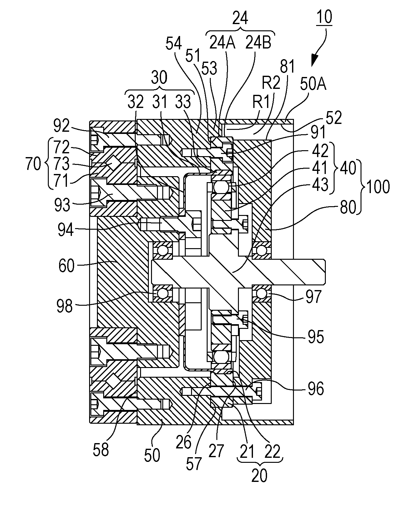
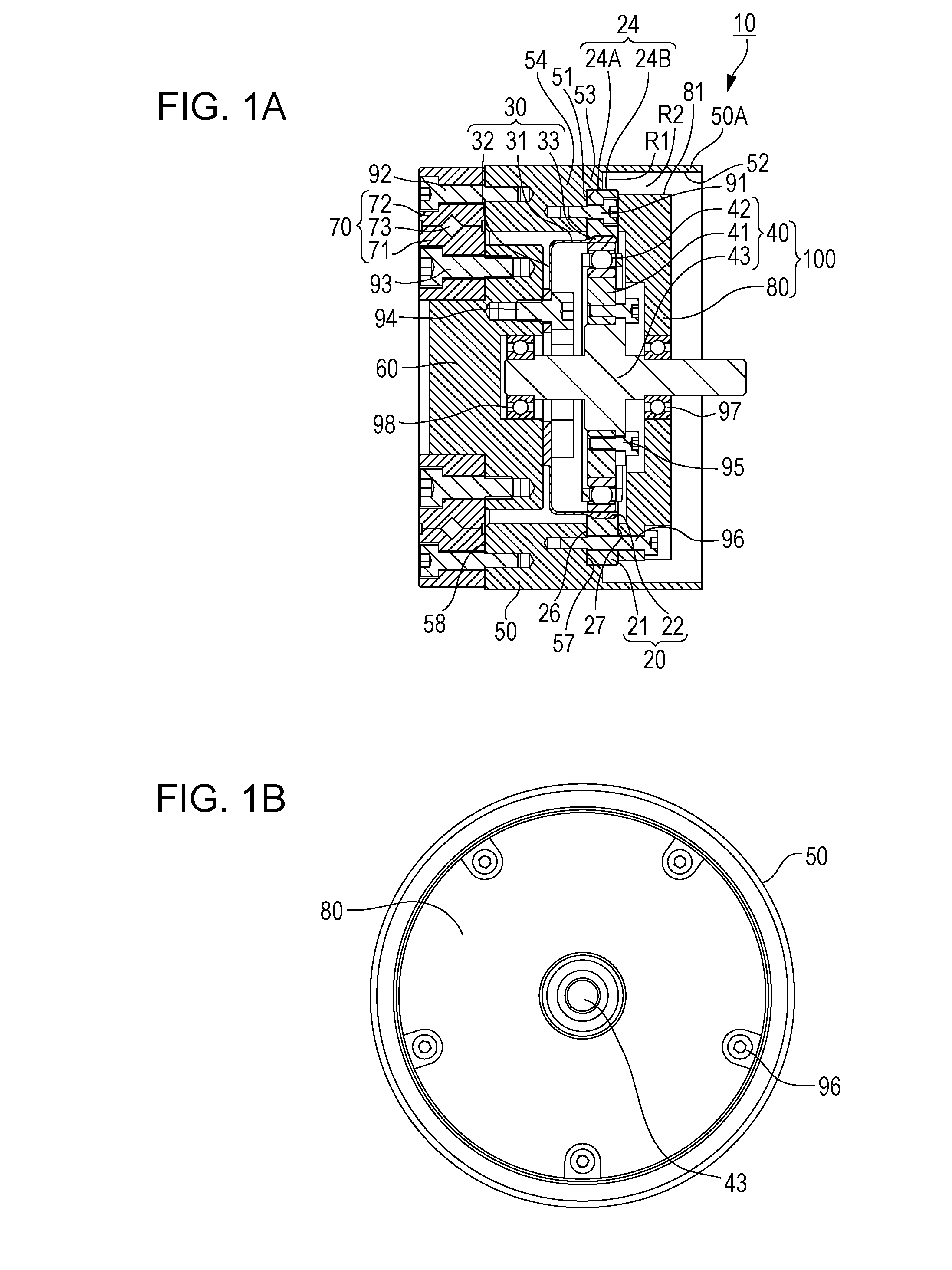
[0027]FIGS. 1A and 1B are explanatory views schematically illustrating the structure of a wave gear device produced by a method of producing according to a first embodiment of the present invention. Out of these drawings, FIG. 1A is a sectional view of the wave gear device, and FIG. 1B is a plan view of the wave gear device.

[0028]A wave gear device 10 includes a rigid internal gear (circular spline) 20, a flex external gear (flex spline) 30, and a wave generator 40.

[0029]The wave gear device 10 also includes a housing 50, an output member 60, a bearing 70, and a support member 80. The housing 50 houses the circular spline 20. The output member 60 serves as a flange of the flex spline 30. The bearing 70 uses a cross roller bearing or the like. The support member 80 serves as a housing of the wave generator 40. The housing 50 has a cylindrical main body 50A, a projection 53, and a projection 54. The projection 53 inwardly projects in a radial direction, which is perpen...

Example

EXAMPLE

[0075]Effects of performance improvement of an articulated multi-axis robot arm, in which the wave gear device 10 produced by the method of producing according to the first embodiment is used, were actually checked.

[0076]A position / path repeatability is one of performance criteria for an articulated multi-axis robot arm (JIS B 8432: Manipulating industrial robots-Performance criteria and related test methods). In this testing, variation in motion path for a given instruction path is observed. This performance criterion significantly affects rotational accuracy of the axes. When the rotational accuracy of the axes is low, the motion path significantly varies for a single instruction path.

[0077]Table lists measured deviation amounts by which the actual motion path deviates from the shortest path between point A and point B in a movement between point A to point B, which are located within a movable range of the articulated multi-axis robot arm. The deviation amount is zero when...

Example

Second Embodiment

[0082]Next, a method of producing the wave gear device according to a second embodiment of the present invention is described. In the above-described first embodiment, the first positioning step and the second positioning step are separately performed with the different jigs J1 and J2, respectively. In the second embodiment, the first positioning step and the second positioning step are simultaneously performed with a common jig.

[0083]FIG. 10 is a view for explaining the first positioning step, the second positioning step, the second securing step, and the third securing step of the method of producing the wave gear device according to the second embodiment. FIGS. 11A to 11C illustrate a common jig. Out of FIGS. 11A to 11C, FIG. 11A is a perspective view of the common jig, FIG. 11B is a sectional view of the common jig, and FIG. 11C is a plan view of the common jig. Since the structure of the wave gear device is similar to that of the first embodiment, the same refe...


PUM

PropertyMeasurementUnit
Lengthaaaaaaaaaa

Abstract

A circular spline is secured to a housing. An output member is positioned relative to the circular spline, an outer race of a bearing is secured to the housing, and an inner race of the bearing is secured to the output member. A flex spline is positioned relative to the circular spline and secured to the output member. A wave generator is positioned relative to the circular spline, and a support member, by which the wave generator is rotatably supported, is secured to the housing.

Description

BACKGROUND OF THE INVENTION[0001]1. Field of the Invention[0002]The present invention relates to a method of producing a wave gear device, by which a circular spline, a flex spline, and a wave generator are positioned, and relates to a wave guide device.[0003]2. Description of the Related Art[0004]Wave gear devices, with which high speed-reduction ratios can be obtained despite their comparatively small sizes, are widely used for speed reducers of motors for driving articulations of robot arms. The wave gear device includes three main components and five positioning components, which position the three main elements.[0005]The three main components are an internal gear referred to as a circular spline, an external gear referred to as a flex spline, and an elliptical cam member referred to as a wave generator. The circular spline is an annular rigid gear having teeth on its inner side. The flex spline is a thin flexible annular gear having teeth on its outer side. Two of the five posi...

Claims


Application Information

Patent Timeline
IPC IPC(8): F16H49/00
CPCF16H2049/003F16H49/001F16H57/023Y10T29/49464Y10T74/19642B25J9/1025
Inventor YAJIMA, AKIRA
Owner CANON KK
Why Eureka
Try Eureka