Walk aerator

a technology of walk aerator and handle assembly, which is applied in the direction of lawn mowers, adjusting devices, agriculture tools and machines, etc., can solve the problems of overheating of such drive systems, and the various operation controls carried on the handle assembly of the aerator may be at less than the optimal height for a particular user

Active Publication Date: 2015-04-23
EXMARK MFG
View PDF13 Cites 7 Cited by
  • Summary
  • Abstract
  • Description
  • Claims
  • Application Information

AI Technical Summary

Benefits of technology

[0006]Yet another aspect of this invention relates to a walk aerator for soil aeration of the ground. The aerator comprises a housing supported for rolling over the ground by a plurality of ground engaging wheels. The housing has an upwardly extending handle assembly which is capable of being gripped by a user who walks on the ground during operation of the aerator. The housing has a downwardly opening cavity. A prime mover is carried on the housing for providing power. A plurality of aerating tools are movably carried on the housing within a first section of the cavity and are operatively connected to the prime mover, the aerating tools engaging the ground and creating soil aeration openings in the ground as the housing rolls over the ground. At least one air cooled traction drive is located within a second section of the cavity. The at least one drive is operatively coupled to the prime mover and to at least one of the ground engaging wheels to self-propel the housing over the ground. The housing contains various vents therein in communication with the second section of the cavity to provide sufficient air flow both into and out of the second section of the cavity to adequately cool the drive.

Problems solved by technology

The Applicants have found that such traction drive systems experience restricted air flow in certain circumstances which may lead to overheating of such drive systems.
Finally, various operational controls carried on the handle assembly of the aerator may be at less than optimal heights for a particular user given the differences in the anatomic heights of different users and whether a particular user is walking on the ground or is being transported on the sulky during a soil aeration operation.

Method used


Image

  • Walk aerator
  • Walk aerator
  • Walk aerator

Examples


Embodiment Construction

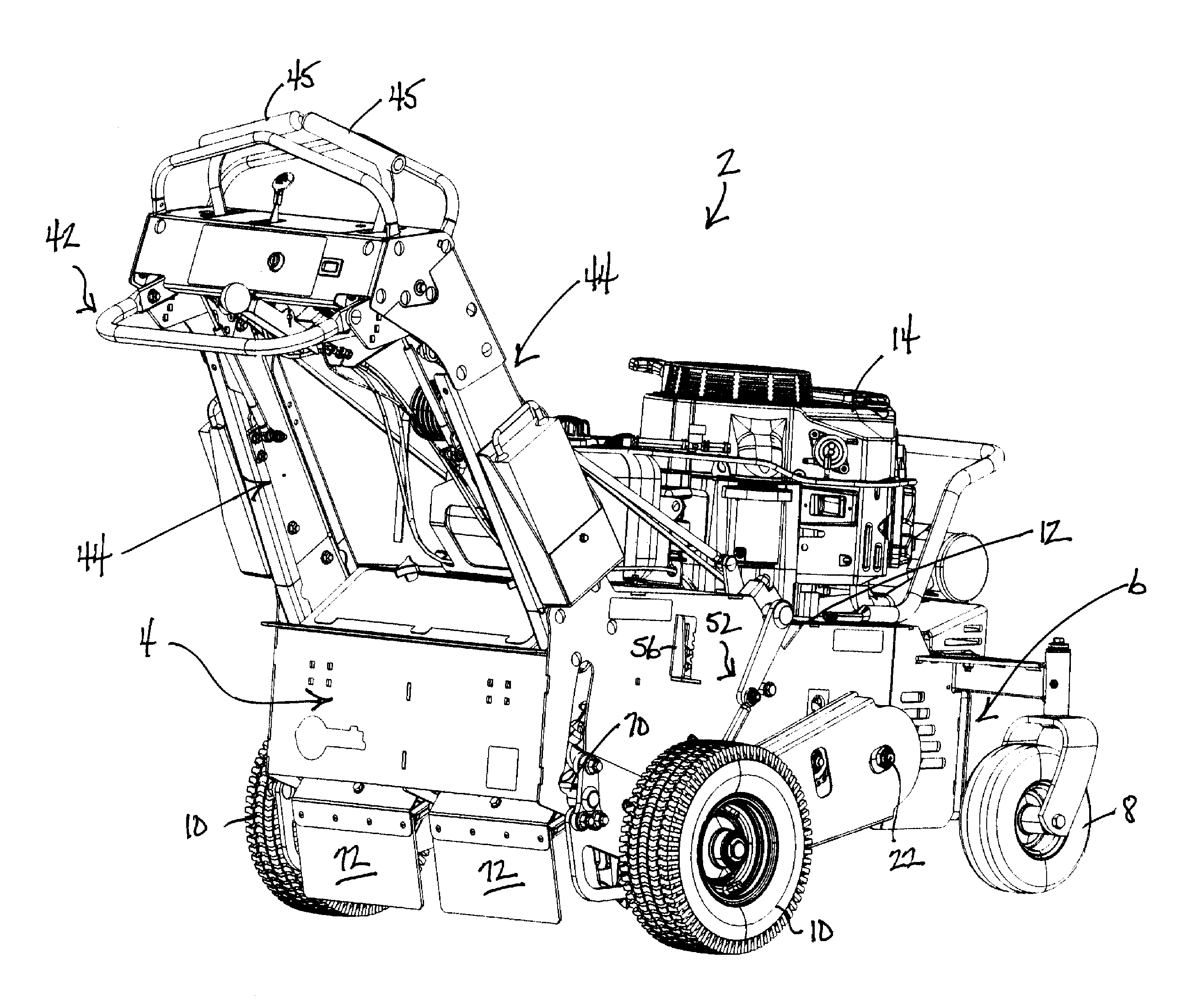
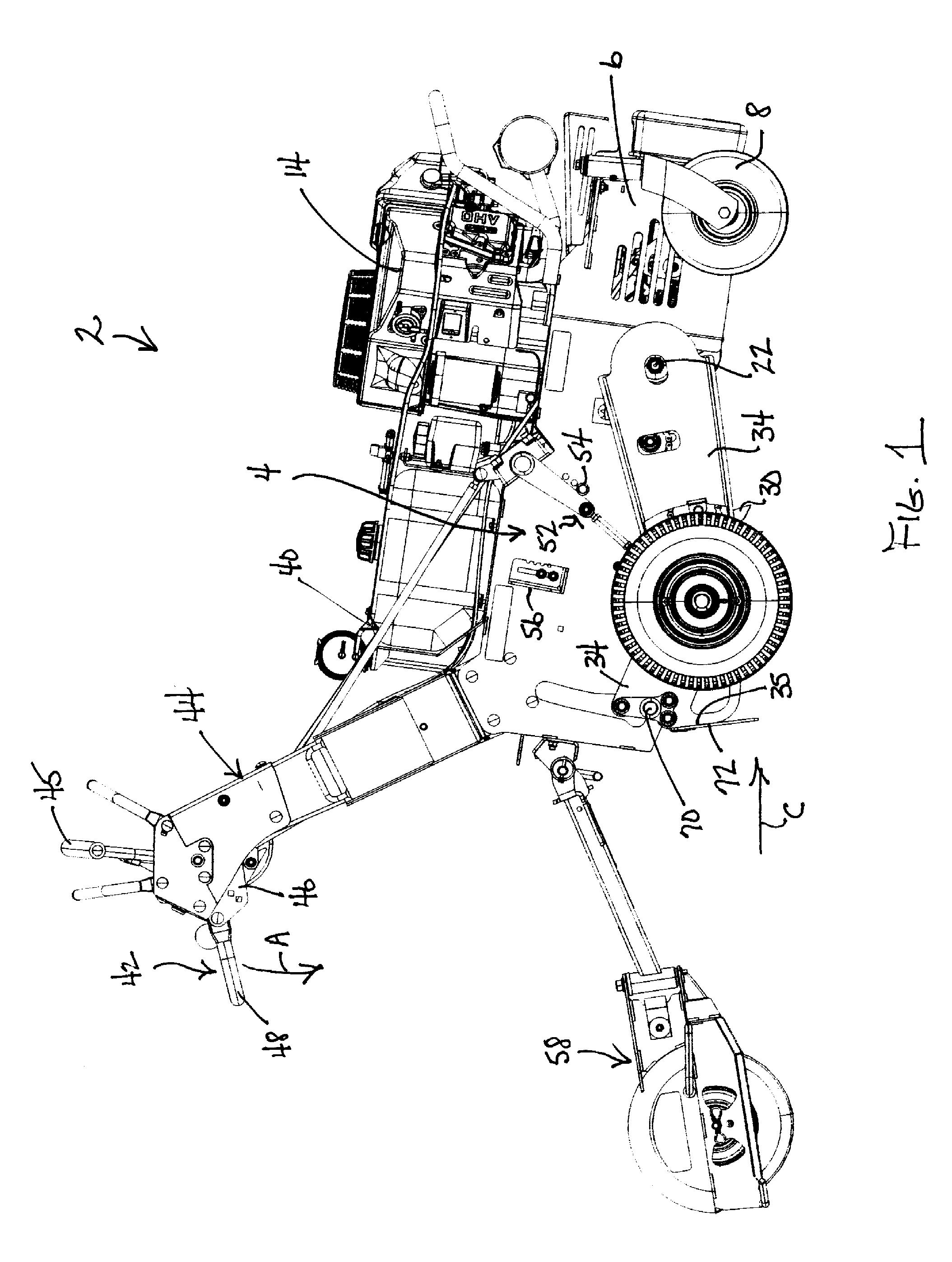
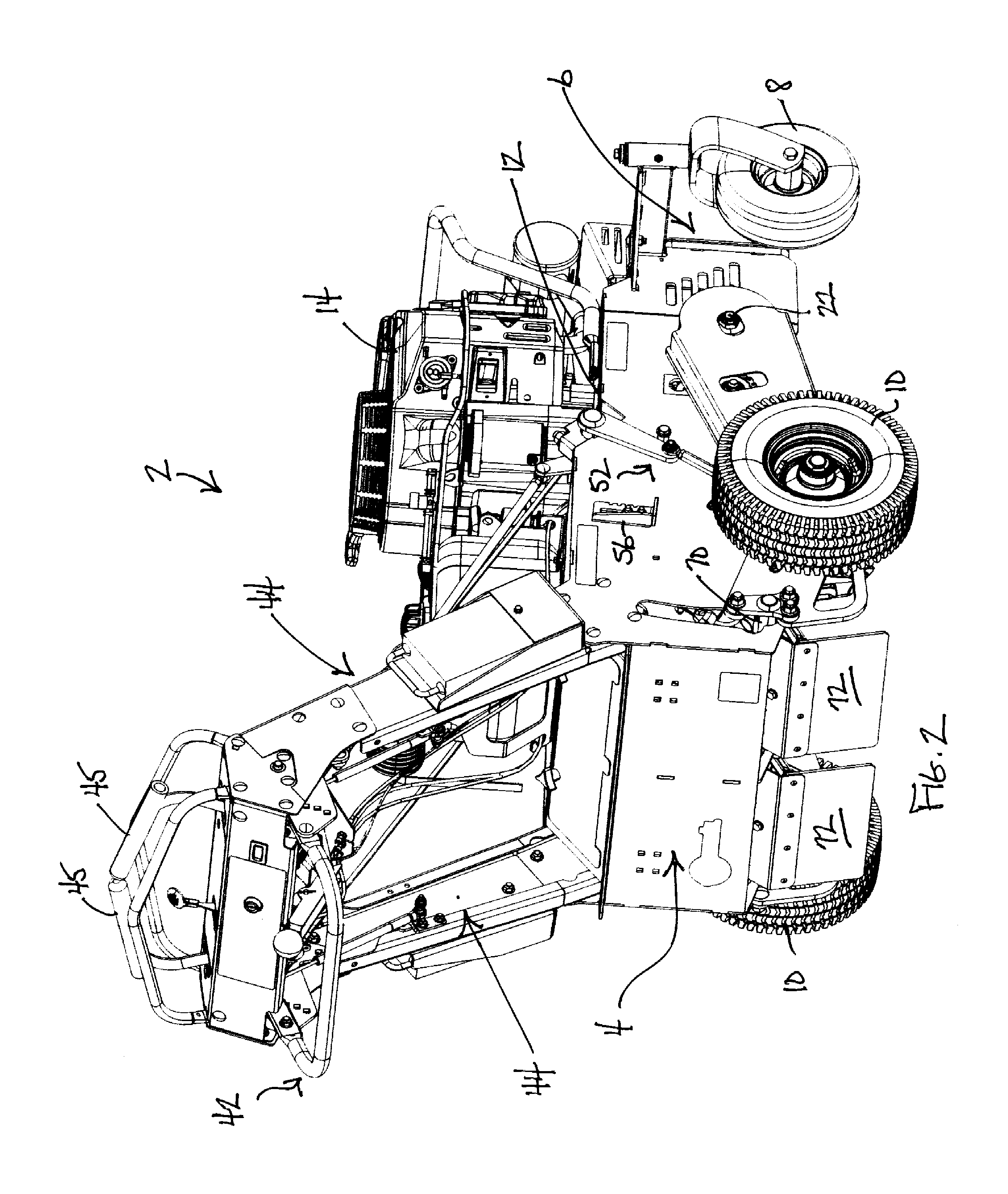
[0016]Referring first to FIGS. 1 and 2, a walk aerator according to this invention is illustrated generally as 2. Aerator 2 comprises a substantially rectangular housing 4 having an inwardly tapered, truncated, V-shaped front end 6. Housing 4 is movably supported for rolling over the ground by a pair of front caster wheels 8 and a pair of rear drive wheels 10. A portion of a top wall of housing 4 forms a prime mover deck 12 that mounts a prime mover 14 thereon. Prime mover 14 preferably comprises an internal combustion engine, but may comprise an electric motor or other suitable power generating device.

[0017]Referring now to FIG. 3, housing 4 defines a substantially enclosed, downwardly opening cavity 18. Cavity 18 is divided into a first front section and a second rear section by cross wall 19. The front section of cavity 18 houses a traction drive system that in one embodiment comprises a pair of side-by-side hydrostatic drives 20. Drives 20 are independent from each other. Each d...


PUM


Abstract

A walk aerator comprises a housing supported by a plurality of wheels that include a pair of drive wheels. The drive wheels are pivotally mounted to the housing to permit the housing to move between operational and transport positions thereof. A control is used to so move the housing with the control having a hand grip whose height above the ground is easily adjustable to accommodate users of different effective heights. A foot guard maintains a relatively constant disposition relative to the ground whether the housing is in its operational or transport position. The housing of the aerator has a vent system and an air gap relative to a prime mover deck which cool a traction drive system contained within the housing.

Description

TECHNICAL FIELD[0001]This invention relates to the field of outdoor power equipment and, more particularly, to a self-propelled walk aerator for soil aeration.BACKGROUND OF THE INVENTION[0002]Walk aerators having various types of ground engaging, soil aerating tools are known for soil aeration. Such aerators are operated by users who grip an upwardly and rearwardly extending handle assembly and walk on the ground behind the aerator during a soil aeration operation. Instead of walking on the ground, the user may be supported on an optional wheeled sulky attached to the aerator. In either case, the aerator is usually self-propelled over the ground by a traction drive system powered by a prime mover mounted on the aerator. While such aerators are effective in aerating smaller areas of turf, they have a number of shortcomings.[0003]For one thing, certain aerator traction drive systems may include one or more transmissions, including hydrostatic or electric drive transmissions, which are...

Claims


Application Information

Patent Timeline
Patent Type & Authority Applications(United States)
IPC IPC(8): A01B45/02A01B63/00
CPCA01B63/008A01B45/02A01B45/026A01B76/00B60K11/06B60K11/08
Inventor BRYANT, CHRISTIAN S.C.BUHR, ALEX W.ANDRE, TIMOTHY D.TATE, JEREMY J.DORN, DANIEL W.
Owner EXMARK MFG
Why Eureka
Try Eureka