Vision-based object sensing and highlighting in vehicle image display systems

a technology of vehicle image display and object sensing, which is applied in the field of image capture and display in vehicle imaging systems, can solve the problems of not being able to determine the parameters of such parameters, not having awareness of the condition where the vehicle could be a potential collision, and objects such as vehicles approaching to the side of the vehicle may be distorted as well

Inactive Publication Date: 2015-04-23
GM GLOBAL TECH OPERATIONS LLC
View PDF9 Cites 56 Cited by
  • Summary
  • Abstract
  • Description
  • Claims
  • Application Information

AI Technical Summary

Benefits of technology

[0004]An advantage of an embodiment is the display of vehicles in a dynamic rearview mirror where the objects such as vehicles are captured by a vision based capture device and objects identified are highlighted for generating an awareness to the driver of the vehicle and a...

Problems solved by technology

In such instance when the view is reproduced on the display screen, due to distortion and other factors associated with the reproduced view, objects such as vehicles approaching to the sides of the vehicle may be distorted as well.
As a result, a user may not have awareness of a condition where the vehicle could be a potential collision to the driven vehicle if the vehicle crossing paths were to continue, as in the insta...

Method used


Image

  • Vision-based object sensing and highlighting in vehicle image display systems
  • Vision-based object sensing and highlighting in vehicle image display systems
  • Vision-based object sensing and highlighting in vehicle image display systems

Examples


first embodiment

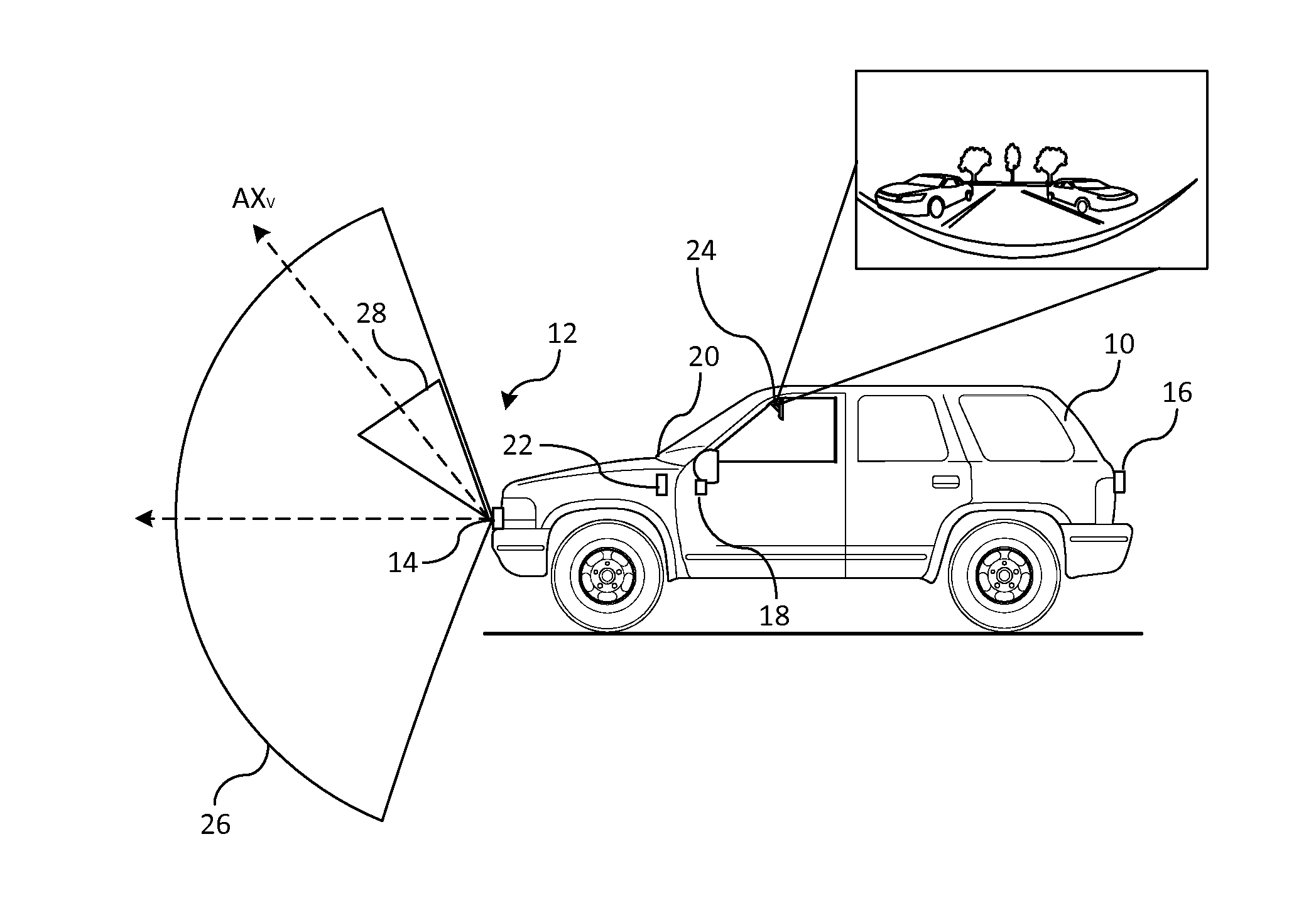
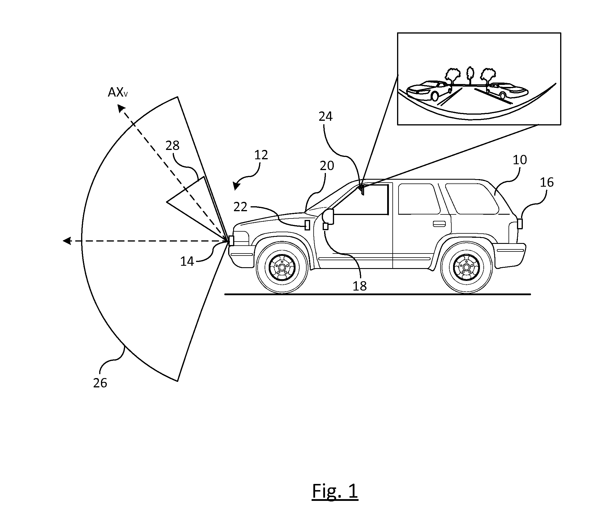
[0089]FIG. 16 illustrates a flowchart of first embodiment for identifying objects on the dynamic rearview mirror display device. While the embodiments discussed herein describe the display of the image on the rearview mirror device, it is understood that the display device is not limited to the rearview mirror and may include any other display device in the vehicle. Blocks 110-116 represent various sensing devices for sensing objects exterior of the vehicle, such as vehicles, pedestrians, bikes, and other moving and stationary objects. For example, block 110 is a side blind zone alert sensor (SBZA) sensing system for sensing objects in a blind spot of the vehicle; block 112 is a parking assist (PA) ultrasonic sensing system for sensing pedestrians; block 44 is a rear cross traffic alert (RTCA) system for detecting a vehicle in a rear crossing path that is transverse to the driven vehicle; and block 116 is a rearview camera for capturing scenes exterior of the vehicle. In FIG. 16, an...

second embodiment

[0092]FIG. 19 illustrates a flowchart of a second embodiment for identifying objects on the rearview mirror display device. Similar reference numbers will be utilized throughout for already introduced devices and systems. Blocks 110-116 represent various sensing devices such as SBZA, PA, RTCA, and a rearview camera. In block 129, a processing unit provides an object overlay onto the image. The object overlay is an overlay that identifies both the correct location and size of an object as opposed to just placing a same sized symbol over the object as illustrated in FIG. 18. In block 120, the rearview display device displays the dynamic image with the object overlay symbols and collective image is then displayed on the rearview display device in block 120.

[0093]FIG. 20 is an illustration of a dynamic image displayed on the dynamic rearview mirror device. Object overlays 132-138 identify vehicles proximate to the driven vehicle that have been identified by one of the sensing systems th...

third embodiment

[0095]FIG. 21 illustrates a flowchart of third embodiment for identifying objects on the rearview mirror display device by estimating a time to collision base on an inter-frame object size and location expansion of an object overlay, and illustrate the warning on the dynamic rearview display device. In block 116, images are captured by an image capture device.

[0096]In block 144, various systems are used to identify objects captured in the captured image. Such objects include, but not limited to, vehicles from devices described herein, lanes of the road based on lane centering systems, pedestrians from pedestrian awareness systems, parking assist system, and poles or obstacles from various sensing systems / devices.

[0097]A vehicle detection system estimates the time to collision herein. The time to collision and object size estimation may be determined using an image based approach or may be determined using a point motion estimation in the image plane, which will be described in detai...


PUM


Abstract

A method of displaying a captured image on a display device of a driven vehicle. A scene exterior of the driven vehicle is captured by an at least one vision-based imaging and at least one sensing device. A time-to-collision is determined for each object detected. A comprehensive time-to-collision is determined for each object as a function of each of the determined time-to-collisions for each object. An image of the captured scene is generated by a processor. The image is dynamically expanded to include sensed objects in the image. Sensed objects are highlighted in the dynamically expanded image. The highlighted objects identifies objects proximate to the driven vehicle that are potential collisions to the driven vehicle. The dynamically expanded image with highlighted objects and associated collective time-to-collisions are displayed for each highlighted object in the display device that is determined as a potential collision.

Description

CROSS-REFERENCE TO RELATED APPLICATIONS[0001]The application is a continuation-in-part of U.S. application Ser. No. 14 / 059,729, filed Oct. 22, 2013.BACKGROUND OF INVENTION[0002]An embodiment relates generally to image capture and display in vehicle imaging systems.[0003]Vehicle systems often use in-vehicle vision systems for rear-view scene detection. Many cameras may utilize a fisheye camera or similar that distorts the captured image displayed to the driver such as a rear back up camera. In such instance when the view is reproduced on the display screen, due to distortion and other factors associated with the reproduced view, objects such as vehicles approaching to the sides of the vehicle may be distorted as well. As a result, the driver of the vehicle may not take notice that of the object and its proximity to the driven vehicle. As a result, a user may not have awareness of a condition where the vehicle could be a potential collision to the driven vehicle if the vehicle crossin...

Claims


Application Information

Patent Timeline
IPC IPC(8): B60Q9/00
CPCB60Q9/008G06V20/58H04N7/188
Inventor ZHANG, WENDEWANG, JINSONGLITKOUHI, BAKHTIAR B.KAZENSKY, DENNIS B.PIASECKI, JEFFREY S.GREEN, CHARLES A.FRAKES, RYAN M.KIEFER, RAYMOND J.
Owner GM GLOBAL TECH OPERATIONS LLC
Why Eureka
Try Eureka