Light emitting diode (LED) devices

a technology of light-emitting diodes and led devices, which is applied in the field of display systems, can solve the problems of poor blue light extraction efficiency of current blue led designs, and achieve the effect of increasing optical power outpu

Inactive Publication Date: 2015-04-23
NANOSYS INC
View PDF18 Cites 86 Cited by
  • Summary
  • Abstract
  • Description
  • Claims
  • Application Information

AI Technical Summary

Benefits of technology

[0023]Suitably, the methods increase the optical power output of the blue LED by at least 10% as com

Problems solved by technology

Blue light extraction efficiency i

Method used


Image

  • Light emitting diode (LED) devices
  • Light emitting diode (LED) devices
  • Light emitting diode (LED) devices

Examples


example 1

Power Output From Blue LEDs by Optical Coupling to a Light Guide Plate

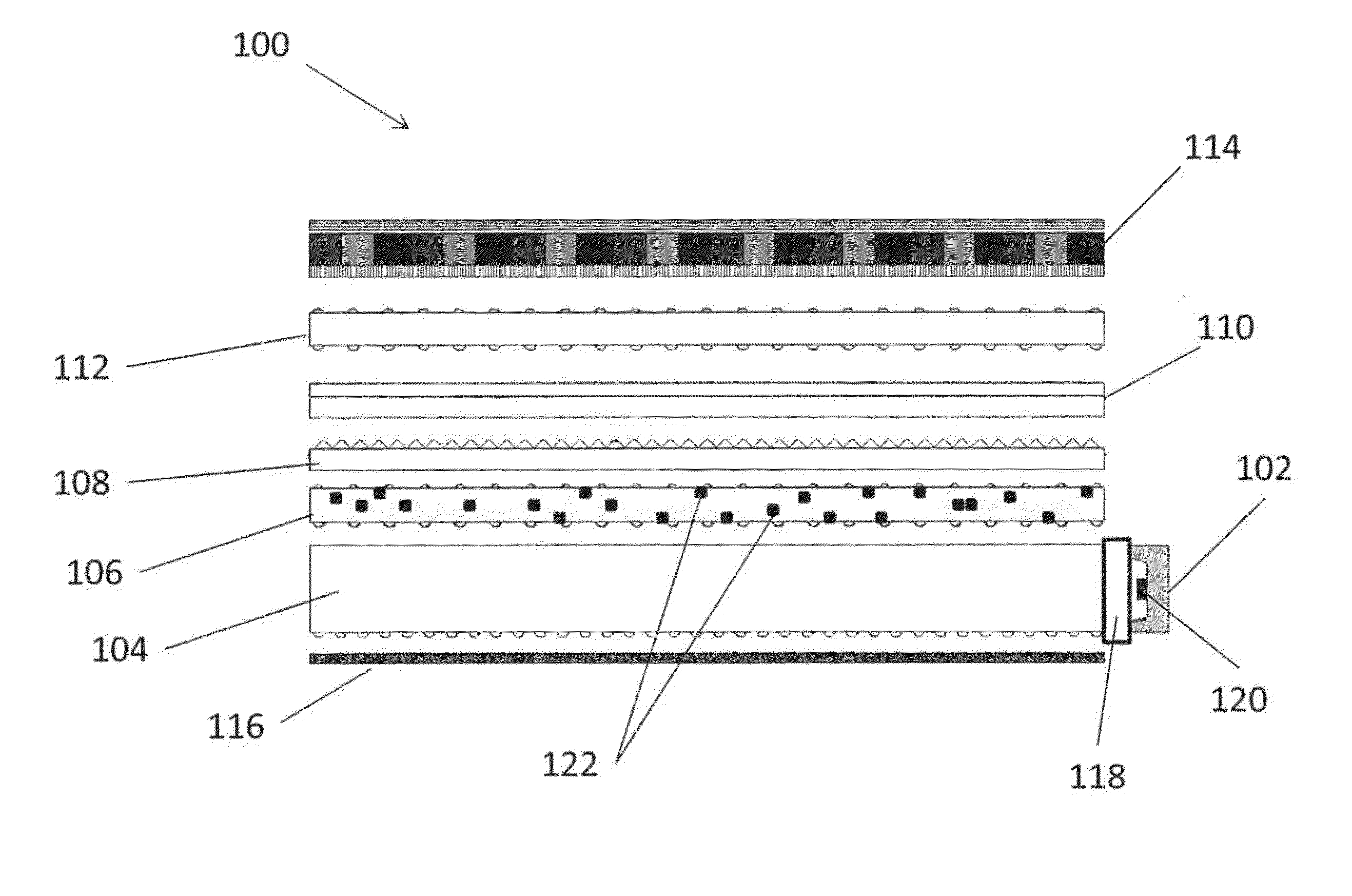
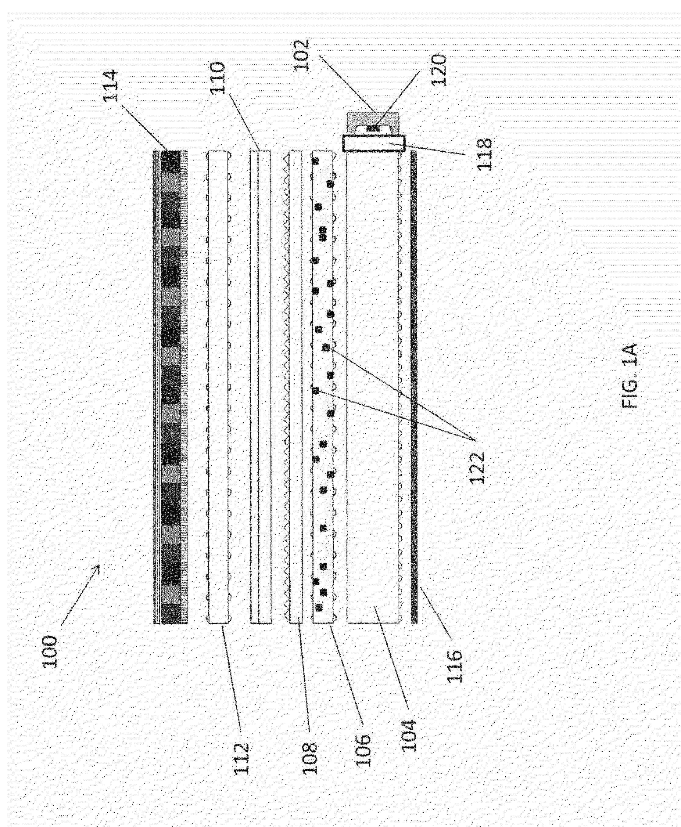
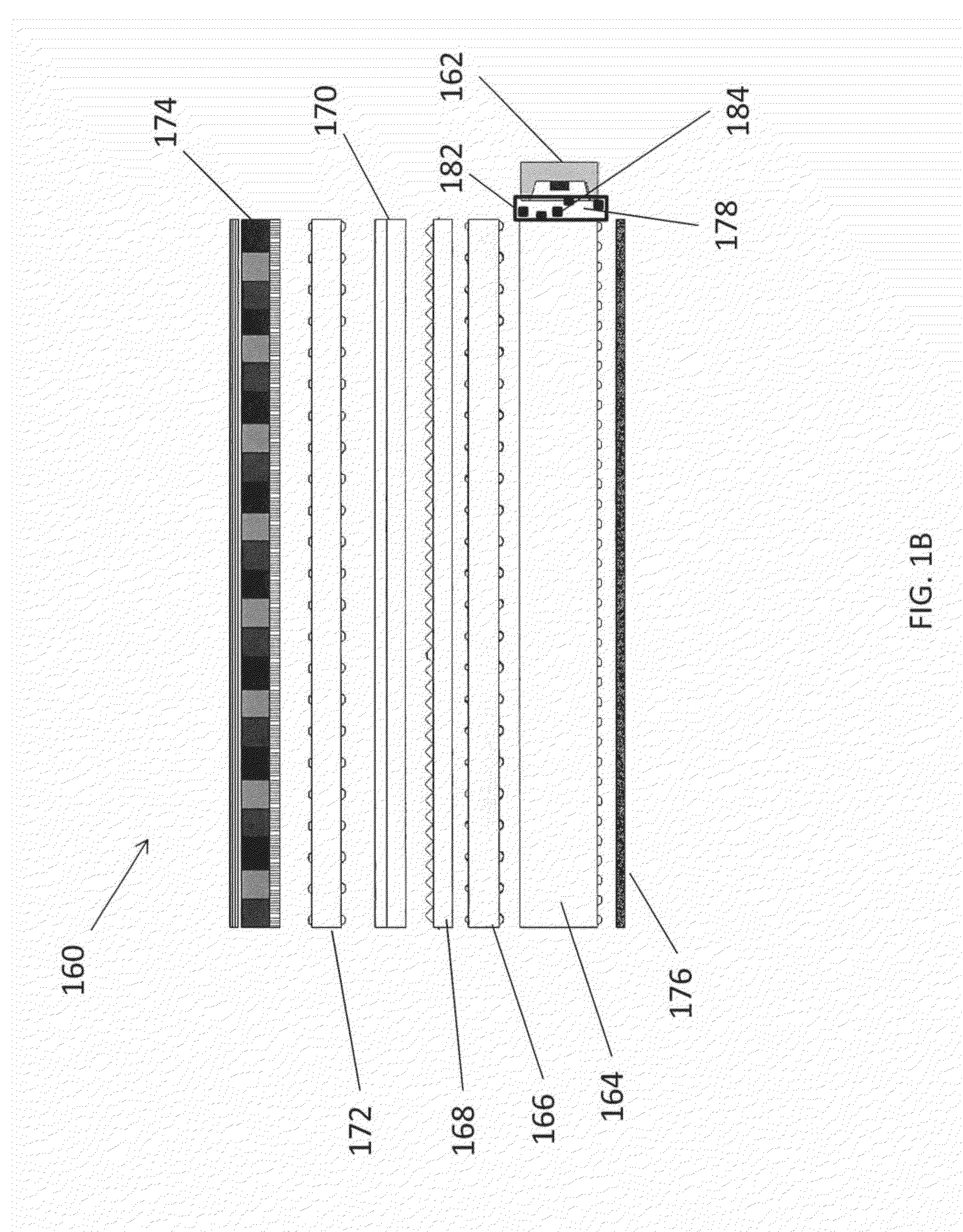
[0108]Generally, liquid crystal displays utilize white LEDs as the light source in the backlight. Most backlights are edge-lit—the white LEDs are placed, on the edge(s) of the backlight. The white LEDs are mounted on a flex strip and placed in close proximity to a light guide plate. White light coming out of the LEDs enters the light guide plate from the edge and, through total internal reflections, is guided across the light guide plate. Extraction features are molded on the surface of the light guide plates to extract light from the light guide plate to enable a uniform distribution of light across the display. Phosphors are often introduced that offer better system efficiency and / or higher color gamut.

[0109]As described herein, luminescent nanocrystals (quantum dots) are dispersed / embedded in a polymeric film or sheet (quantum dot enhancement film (QDEF)) and placed on top of a light guide plate. White LEDs are...


PUM


Abstract

Disclosed teem are display systems comprising light-emitting, diodes (LEDs), suitably blue light LEDs, which demonstrate increased optical power output. In embodiments, the display systems include compositions comprising phosphors, including luminescent nanocrystals.

Description

CROSS-REFERENCE TO RELATED APPLICATIONS[0001]The present invention claims the benefit of U.S. Provisional Patent Application No. 61 / 892,027, filed Oct. 17, 2013, the disclosure of which is incorporated by reference herein in its entirety.BACKGROUND OF THE INVENTION[0002]1. Field of the Invention[0003]The present invention relates to display systems comprising light-emitting diodes (LEDs), suitably blue light LEDs, which demonstrate increased optical power output. In embodiments, the display systems include compositions comprising phosphors, including luminescent nanocrystals.[0004]2. Background of the Invention[0005]In liquid crystal display (LCD) backlights, white LEDs are typically[0006]utilized as a light source. In one configuration, the LEDs are arranged around the edge or perimeter of the display. In such the case of edge-lit backlights, light emanating from the LEDs enters a light guide, plate which distributes white light uniformly across the display. White LED package desig...

Claims


Application Information

Patent Timeline
IPC IPC(8): F21V8/00F21K2/00
CPCG02B6/0053F21K2/00G02B6/0055G02B6/0051G02F1/133615H01L33/502G02B6/005G02B6/0073G02F1/133614
Inventor CHEN, JIANDUBROW, ROBERT S.GENSLER, STEVENHARTLOVE, JASONLEE, ERNESTWILSON, ROBERT EDWARD
Owner NANOSYS INC
Why Eureka
Try Eureka