
Sacroiliac Joint Implants and Implantation Methods

a sacroiliac joint and implanting technology, applied in the field of sacroiliac joint surgery, can solve the problems of large stress on the si joint, low back and radiating buttock and leg pain in patients, and achieve the effect of reducing the risk of surrounding tissue trauma during implantation

Inactive Publication Date: 2015-04-23
INST FOR MUSCULOSKELETAL SCI & EDUCATION
View PDF29 Cites 43 Cited by
  • Summary
  • Abstract
  • Description
  • Claims
  • Application Information

AI Technical Summary

Benefits of technology

This patent describes a new method and device for fixing a joint called the sacroiliac joint using a minimally invasive technique. The device includes an implant with a spacer and a planar member that are designed to stabilize the joint. The implant is fixed in place using fastening elements. This new technique provides a safer and less invasive way to fix the sacroiliac joint.

Problems solved by technology

The SI joints provide support for the entire weight of the upper body when a human stands erect, which creates a large amount of stress on the SI joints.
Therefore, these joints are susceptible to injury and degeneration.
Acute and chronic injury, degeneration, and laxity of the supporting ligaments of the SI joint can result in low back and radiating buttock and leg pain in afflicted patients.
A significant problem with certain conventional methods for SI joint fixation is that they require a surgeon to have direct access and a view of the SI joint.
Thus, some conventional SI joint fixation techniques require the use of what is commonly referred to as “open surgery,” and result in significant trauma and disruption to the tissues and skin surrounding the SI joint.
Open procedures increase the risk of damage to major nerves, blood vessels, ligaments, and muscles around the incision site.
Moreover, open procedures increase operative, hospitalization, and recovery time due to the extensive soft tissue damage resulting from open surgery techniques.
Conventional lateral MIS procedures still may result in significant trauma to the major nerves, blood vessels, and muscle groups of the hip.
While current posterior MIS approaches eliminate damage to the soft tissues and neurovascular system of the lateral hip, they still carry a significant risk of trauma to the spinal nerves and major back and hip ligaments.

Method used


Image

  • Sacroiliac Joint Implants and Implantation Methods
  • Sacroiliac Joint Implants and Implantation Methods
  • Sacroiliac Joint Implants and Implantation Methods

Examples


Embodiment Construction

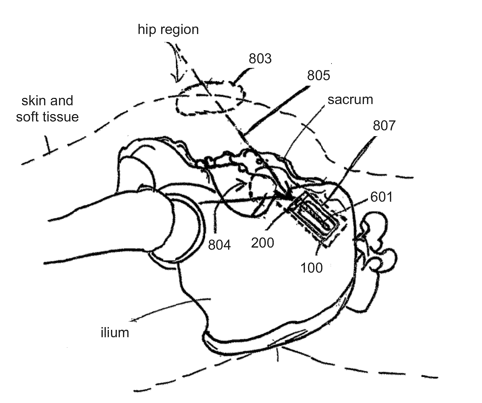
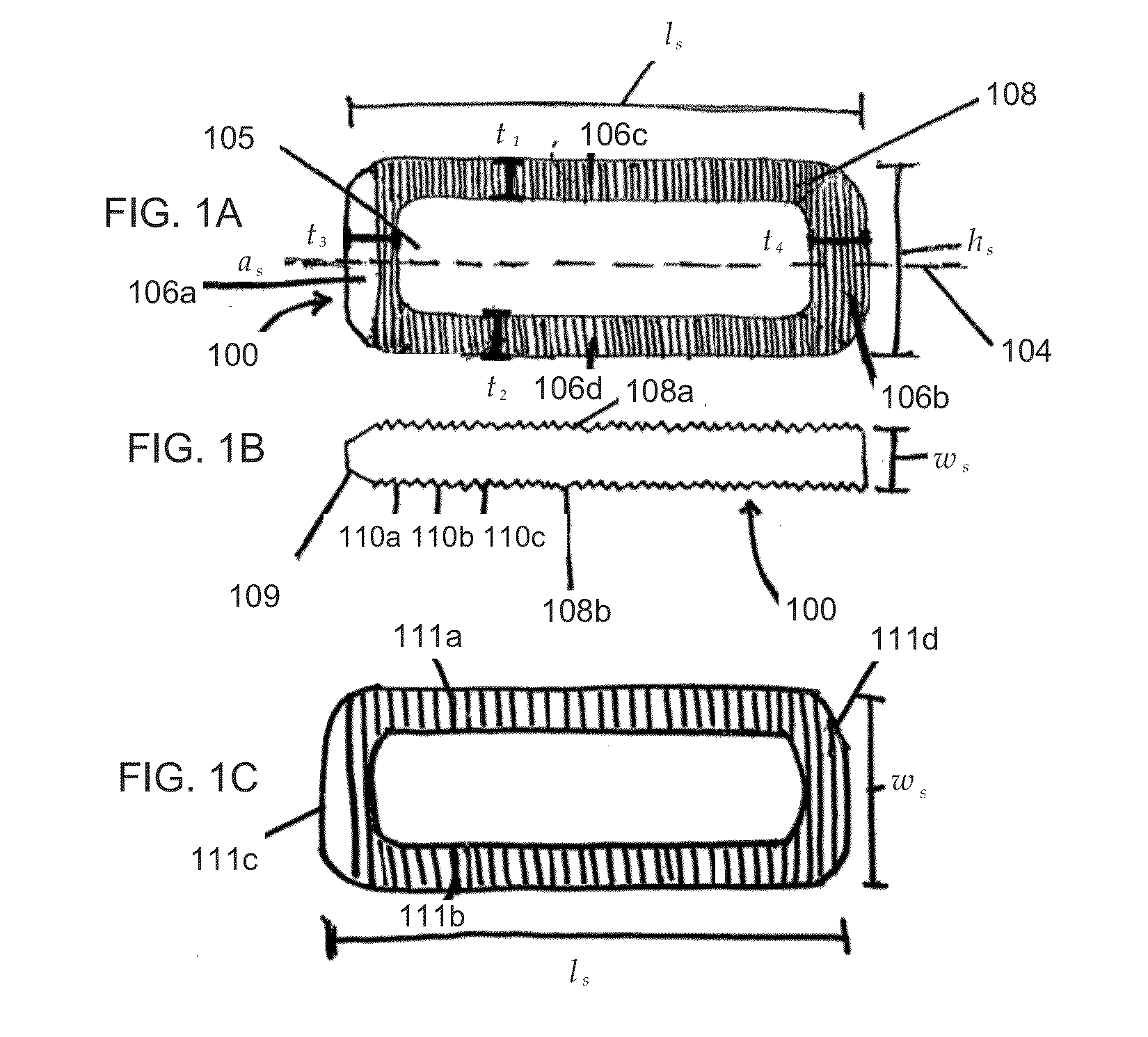
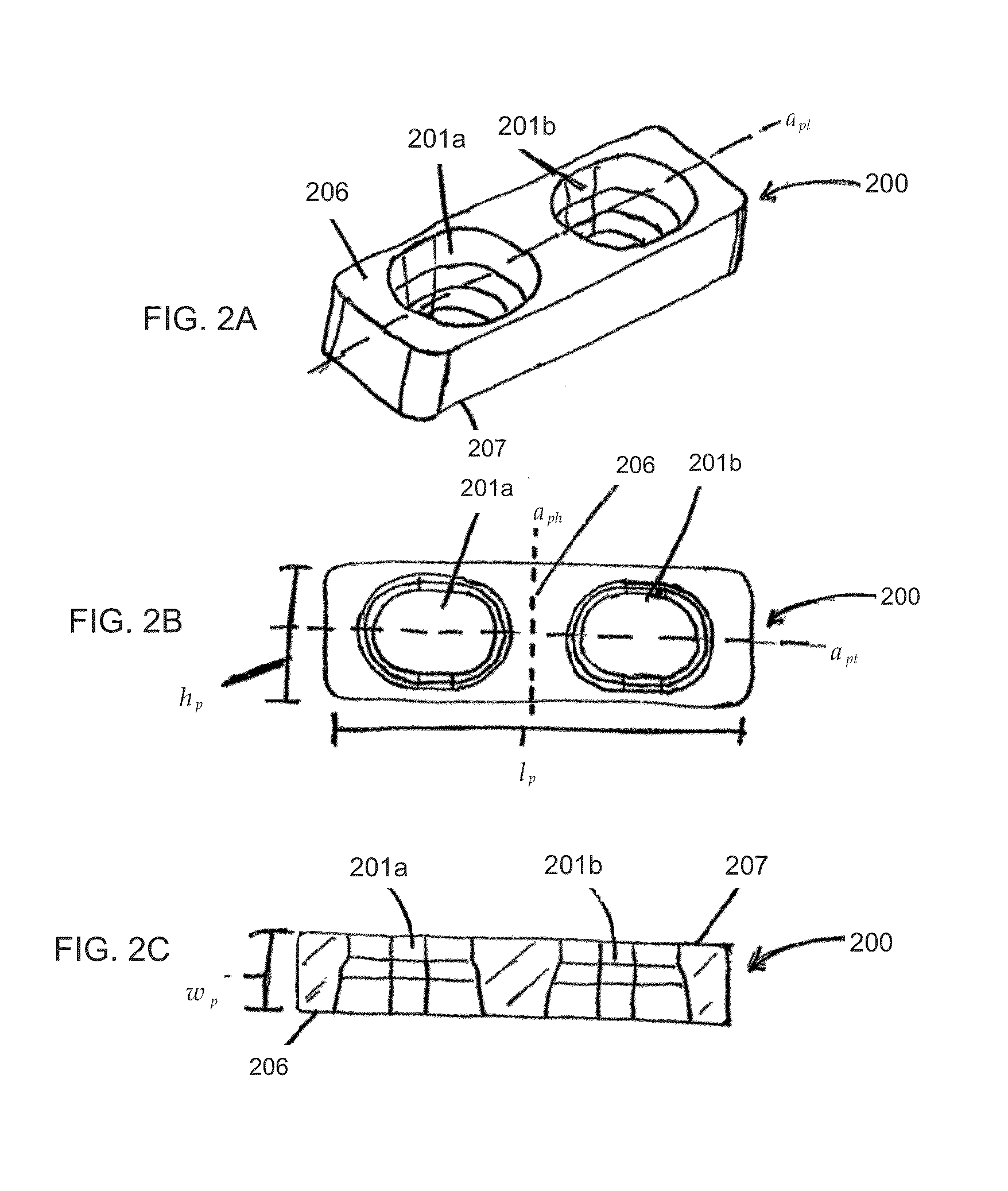
[0031]The following discussion includes a description of a joint implant system, related components, and exemplary methods of employing the implant system. Generally, FIGS. 1A-7D and 10A-11C illustrate several embodiments of the disclosed SI implant system. FIGS. 8-9 and 16-17 illustrate the use of the several embodiments illustrated in FIGS. 1A-7D and 10A-11C in a patient in need of SI joint fixation. FIGS. 12-15 illustrate exemplary tools for preparing the SI joint space for receiving a SI joint implant. While several embodiments are described in connection with these drawings, there is no intent to limit the disclosure to the embodiment or embodiments illustrated therein.

[0032]I. Sacroiliac Implant System

[0033]The SI implant system has a spacer, which serves as a medium to stabilize and promote bone growth in the SI joint to promote SI joint fusion.

[0034]The spacer contains or is operatively coupled to one or more stabilizing elements. The spacer is operatively coupled to a plana...


PUM


Abstract

Sacroiliac (SI) joint implants for promoting SI joint fusion and methods of their delivery are described herein. The SI joint implant has a spacer operatively coupled to a planar member having tapered holes to receive fastening elements. When placed in the SI joint, the spacer engages the articular surfaces of the SI joint while the plate traverses the SI joint. The implant is held in place fastening elements, which are inserted through the tapered holes in the planar member. The implant is delivered via an inferior inlet MIS procedure, wherein the SI joint is accessed through an inlet inferior to the SI joint.

Description

CROSS REFERENCE TO RELATED APPLICATION[0001]This application claims priority to U.S. Provisional Application Ser. No. 61 / 893,027 filed on Oct. 18, 2013, the contents of which are hereby incorporated in their entirety.FIELD OF THE INVENTION[0002]The present invention relates generally to surgical procedures for a sacroiliac (SI) joint, and more specifically, to SI joint implants and minimally invasive surgical (MIS) procedures for delivering SI joint implants.BACKGROUND OF THE INVENTION[0003]Sacroiliac (SI) joints are located between the sacrum and the right and the left iliac bones, respectively. The SI joints provide support for the entire weight of the upper body when a human stands erect, which creates a large amount of stress on the SI joints. Therefore, these joints are susceptible to injury and degeneration. Acute and chronic injury, degeneration, and laxity of the supporting ligaments of the SI joint can result in low back and radiating buttock and leg pain in afflicted patie...

Claims


Application Information

Patent Timeline
IPC IPC(8): A61F2/30
CPCA61F2002/30622A61F2/30A61B17/68A61F2002/30995A61B17/1659
Inventor AKSU, KENAN
Owner INST FOR MUSCULOSKELETAL SCI & EDUCATION
Learn More