Inlet System for a Precooler

a technology of precooler and inlet system, which is applied in the direction of machines/engines, efficient propulsion technologies, combustion air/fuel air treatment, etc., can solve the problems of unfavorable engine performance, unfavorable engine performance, and inability to meet the needs of passengers, so as to improve the performance of the engine system

Active Publication Date: 2015-04-30
THE BOEING CO
View PDF18 Cites 7 Cited by
  • Summary
  • Abstract
  • Description
  • Claims
  • Application Information

AI Technical Summary

Benefits of technology

[0013]In another illustrative embodiment, an inlet system comprises an inlet, a leading edge of the inlet, and a vane associated with the inlet. The leading edge of the inlet is positioned relative to a direction of air flow such that a total pressure of air along the leading edge of the inlet is equalized within selected tolerances. The vane has a vane leading edge positioned relative to the direction of the air flow such that the total pressure of the air along the vane leading edge is equalized within the selected tolerances. Undesired spillage from the inlet is reduced when the total pressure of the air along the leading edge of the inlet and the vane leading edge is equalized within the selected tolerances.
[0014]In yet another illustrative embodiment, a method for improving performance of an engine system is provided. An air flow is created through a fan duct in the engine system. A total pressure of air is equalized along a leading edge of an inlet in the engine system within selected tolerances such that a disruption of the air flow through the fan duct is reduced to improve the performance of the engine system.

Problems solved by technology

In some cases, the bleed air may be too hot for use in the cabin, in other lower temperature areas of the aircraft, or in other types of areas.
However, in a low-flow state or a no-flow state, the inlet may disrupt the flow of air through the fan duct of the engine more than desired.
The variance in total pressure may result in undesired spillage during the low-flow state or the no-flow state based on current configurations for inlets.
For example, undesired spillage may occur when a portion of the air flowing through the fan duct enters the inlet and then flows back out into the fan duct due to the low-flow state or the no-flow state.
In other words, the air flows back out through the inlet into the fan duct, which causes an undesired disruption in air flow through the fan duct.
This disruption in air flow may decrease aerodynamic performance more than desired.
Due to limitations on how quickly flow can be slowed down, or diffused, the duct used to connect an inlet to a precooler may be longer than desired.
However, with the increasing size of precoolers, mounting these precoolers as far aft as needed may be more difficult than desired due to space limitations and physical constraints inside the nacelle of the engine.
The pylon structure may extend inside of the nacelle in a manner that decreases the space available for mounting precoolers.

Method used


Image

  • Inlet System for a Precooler
  • Inlet System for a Precooler
  • Inlet System for a Precooler

Examples


Embodiment Construction

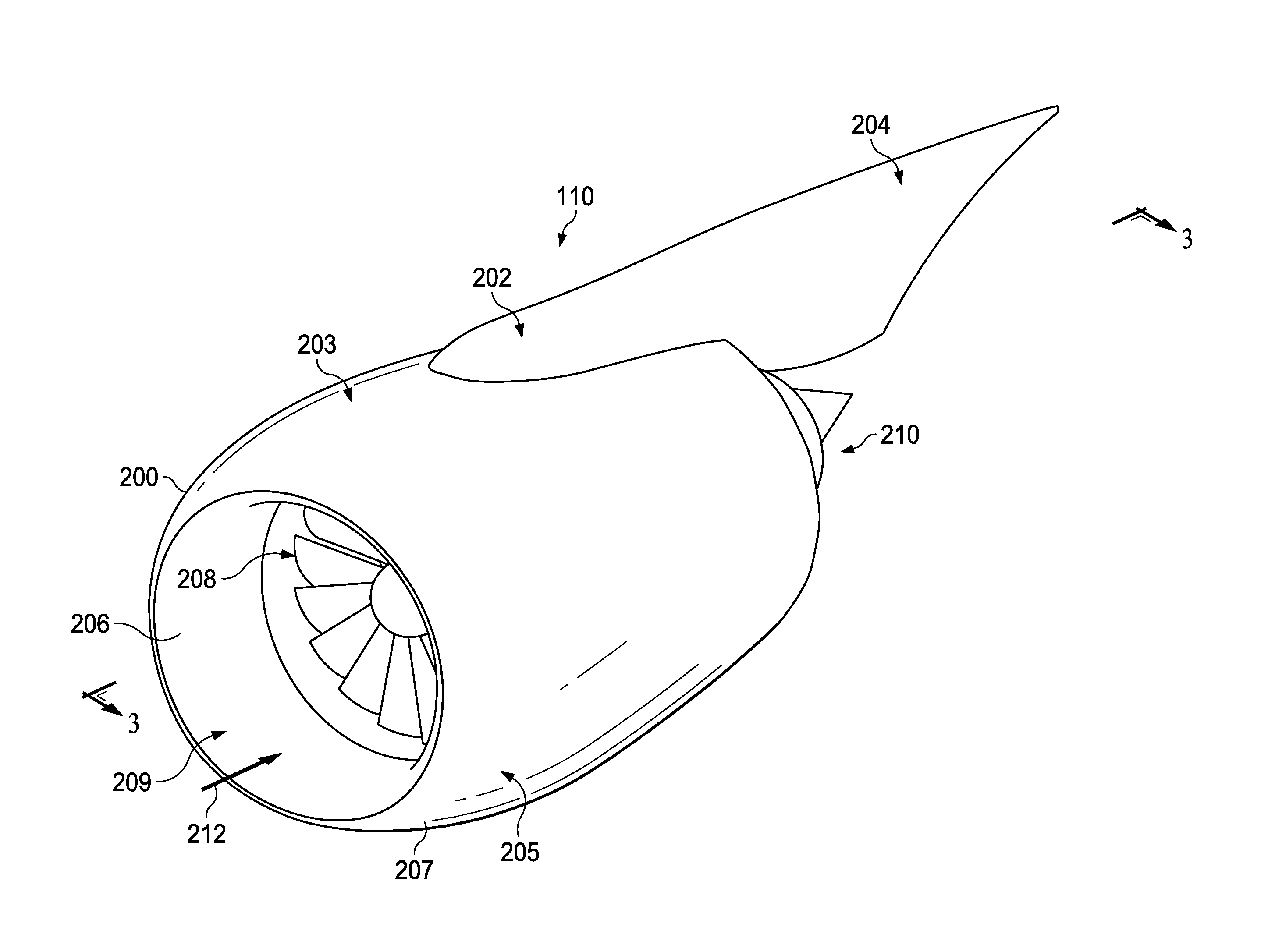
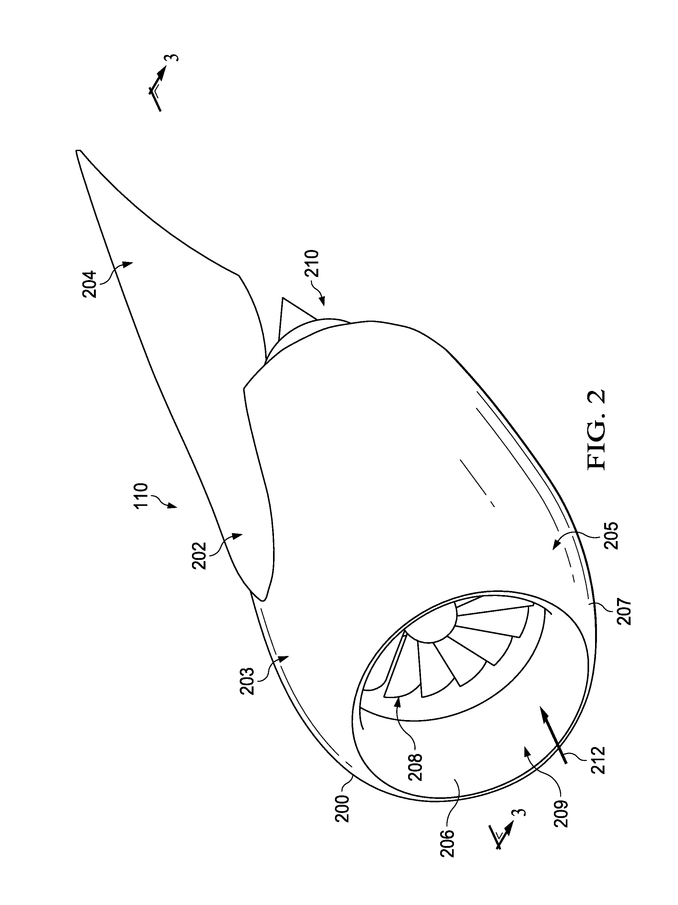
[0033]The illustrative embodiments recognize and take into account different considerations. For example, the illustrative embodiments recognize and take into account that it may be desirable to have an inlet system that does not disrupt the flow of air through the fan duct of an engine more than desired. By reducing the disruption to the flow of air caused by the inlet system, performance of the engine may be improved. In particular, this type of inlet system may improve the performance of the engine by reducing total pressure losses, static pressure distortion, or both.

[0034]Further, the illustrative embodiments recognize and take into account that it may be desirable to have an inlet system that allows a precooler to be mounted further forward than is currently possible using current configurations for inlets. By mounting the precooler further forward, away from the location where the structural pylon extends within the nacelle of an engine, larger precoolers may be installed wit...


PUM


Abstract

An apparatus comprises a leading edge of an inlet. The leading edge of the inlet is positioned relative to a direction of air flow such that a total pressure of air along the leading edge of the inlet is equalized within selected tolerances.

Description

BACKGROUND INFORMATION[0001]1. Field[0002]The present disclosure relates generally to inlets and, in particular, to an inlet for a precooler in an engine system of a vehicle. Still more particularly, the present disclosure relates to a method and apparatus for improving performance of the vehicle using an inlet having a swept leading edge.[0003]2. Background[0004]In a turbofan engine, air is drawn into a main inlet of the engine by a fan. The fan pressurizes the flow of air and the air flows from the fan in two portions. A first portion of the air flows through the core of the engine. A second portion of the air flows through a fan duct that surrounds the core of the engine.[0005]In certain situations, air may be “bled” from the core of an engine of an aircraft to supply an environmental control system (ECS), an anti-icing system, some other type of system of the aircraft, or a combination thereof. The air bled from the core of the engine may be referred to as “bleed air.”[0006]The ...

Claims


Application Information

Patent Timeline
Patent Type & Authority Applications(United States)
IPC IPC(8): B64D33/02F02C7/04
CPCB64D33/02B64D2033/0226B64D2033/024F02C7/04B64D13/02B64D13/06B64D2013/0603B64D2241/00F02C6/04F02C7/18F05D2250/51F05D2260/213Y02T50/60Y10T137/0536F02C6/08
Inventor TRETOW, PAUL R.WILLIE, ROBERT HENRYROBINSON, DONALD EDWIN
Owner THE BOEING CO
Why Eureka
Try Eureka