Dual drive plate damper for hybrid electric vehicles

a technology of hybrid electric vehicles and dampers, which is applied in the direction of mechanical actuated clutches, couplings, interlocking clutches, etc., can solve the problems of reducing fuel economy and performance, adding length and cost to the damper, etc., and achieves low production and installation costs , the effect of easy installation

Active Publication Date: 2015-04-30
FORD GLOBAL TECH LLC
View PDF5 Cites 9 Cited by
  • Summary
  • Abstract
  • Description
  • Claims
  • Application Information

AI Technical Summary

Benefits of technology

[0010]The assembly requires a short axial length, is easy to install on engine crank shaft, and has low production and installation costs.
[0011]The mechanical properties, such as flexural and torsional stiffness of the arms and cutouts of the drive plates can be designed to provide compliance and reduce cyclic torque (due to engine cylinder firing events) and load in both torsional directions on downstream components.

Problems solved by technology

The damper adds length and cost of the powertrain.
The damper also increases powertrain inertia protentially reducing fuel economy and performance.

Method used


Image

  • Dual drive plate damper for hybrid electric vehicles
  • Dual drive plate damper for hybrid electric vehicles
  • Dual drive plate damper for hybrid electric vehicles

Examples


Embodiment Construction

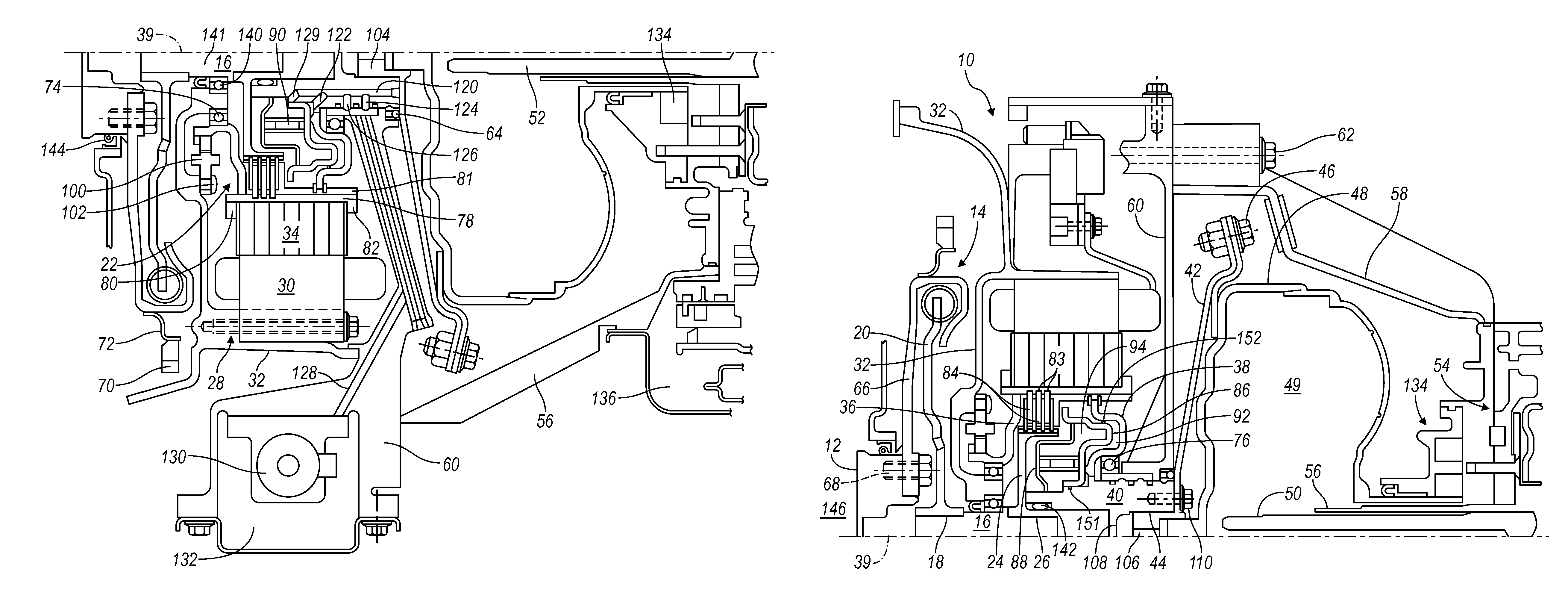
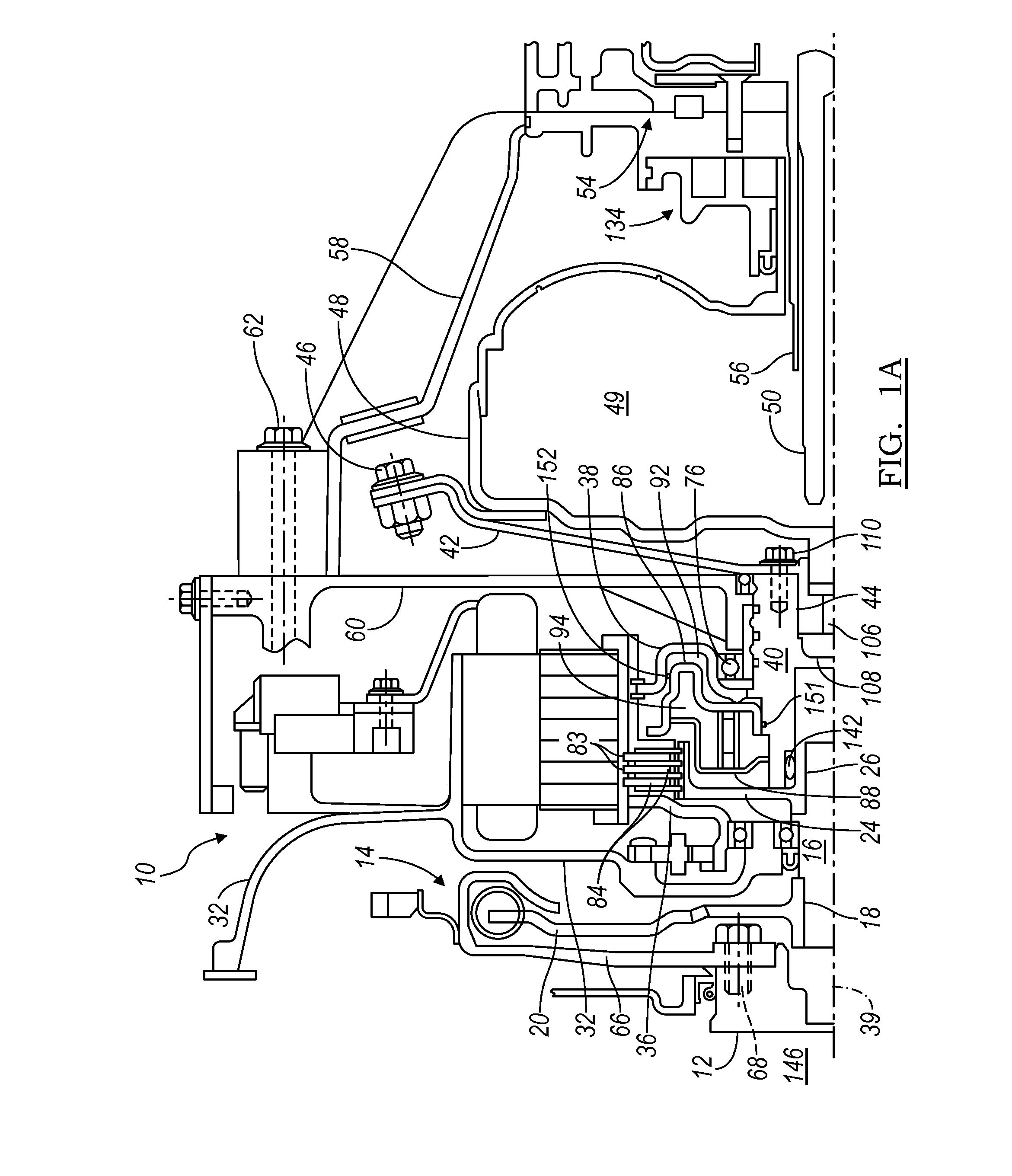
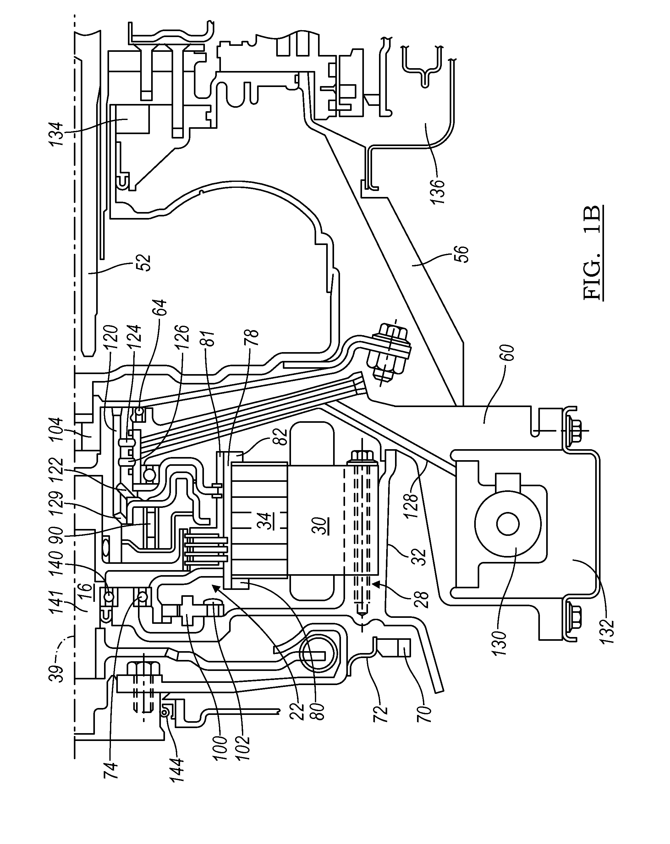
[0019]FIGS. 1A and 1B illustrate a module 10 of a powertrain for a hybrid electric vehicle that includes an engine having a rotary output 12; a torsional damper 14, secured to the engine output 12; an input shaft 16, secured by a spline 18 to an output 20 of damper 14; a disconnect clutch 22, supported on a clutch hub 24 that is secured by a spline 26 to input shaft 16; an electric machine 28, which includes a stator 30 bolted to a front bulkhead 32 and a rotor 34 supported by a first leg 36 and a second leg 38 for rotation about an axis 39; a rotor hub 40, secured preferably by a weld to leg 38; and a flexplate 42, secured at one end by a spline connection 44 to rotor hub 40 and secured at the opposite end by bolts 46 to a torque converter casing 48, which encloses a hydrokinetic torque converter 49. The electric machine 28 may be an electric motor or an electric motor-generator.

[0020]Torque converters suitable for use in the powertrain are disclosed in and described with reference...


PUM


Abstract

An assembly includes an engine output concentric with an axis, an input, a starting gear, a first drive plate secured to the engine output, including a rim supporting the starting gear, and arms extending radially outward from the axis, and a second drive plate rotatably secured to the input, and secured to the first drive plate at a location spaced radially outward from the axis.

Description

BACKGROUND OF THE INVENTION[0001]1. Field of the Invention[0002]This invention relates to a powertrain of hybrid electric vehicles, particularly to a powertrain module that can be installed between and secured to an engine output and a transmission input.[0003]2. Description of the Prior Art[0004]Hybrid electric vehicles (HEVs) have both an internal combustion engine and an electric machine, which are alternately, or in combination, used to propel the vehicle. A variety of different powertrains are used in hybrid vehicles such as a parallel configuration, in which the engine is connected to the motor by a disconnect clutch with the motor driving a torque converter input of an automatic power transmission. The transmission has an output which is connected to a differential coupled to the two driven wheels of the vehicle.[0005]A need exists in the industry for a hybrid electric powertrain that includes a modular subassembly for use with a variety of engines and transmissions, such tha...

Claims


Application Information

Patent Timeline
Patent Type & Authority Applications(United States)
IPC IPC(8): F16D13/38F16D25/0635
CPCF16D25/0635F16D13/38B60K6/38F16D1/076F16D3/50B60K6/26B60K6/387B60K6/40F16F15/30Y02T10/62
Inventor BREVICK, JOHN E.FRAIT, STEVEN A.DEVEREAUX, KEITH A.
Owner FORD GLOBAL TECH LLC
Why Eureka
Try Eureka