
Transit fare collection system

a technology of automated fare collection and transit terminal, which is applied in the direction of ticket-issuers, instruments, computing, etc., can solve the problems of burdening passengers, system strain on associated transportation terminals, and inability to store value fare cards

Active Publication Date: 2015-04-30
MONTEALEGRE HAROLDO J
View PDF6 Cites 35 Cited by
  • Summary
  • Abstract
  • Description
  • Claims
  • Application Information

AI Technical Summary

Benefits of technology

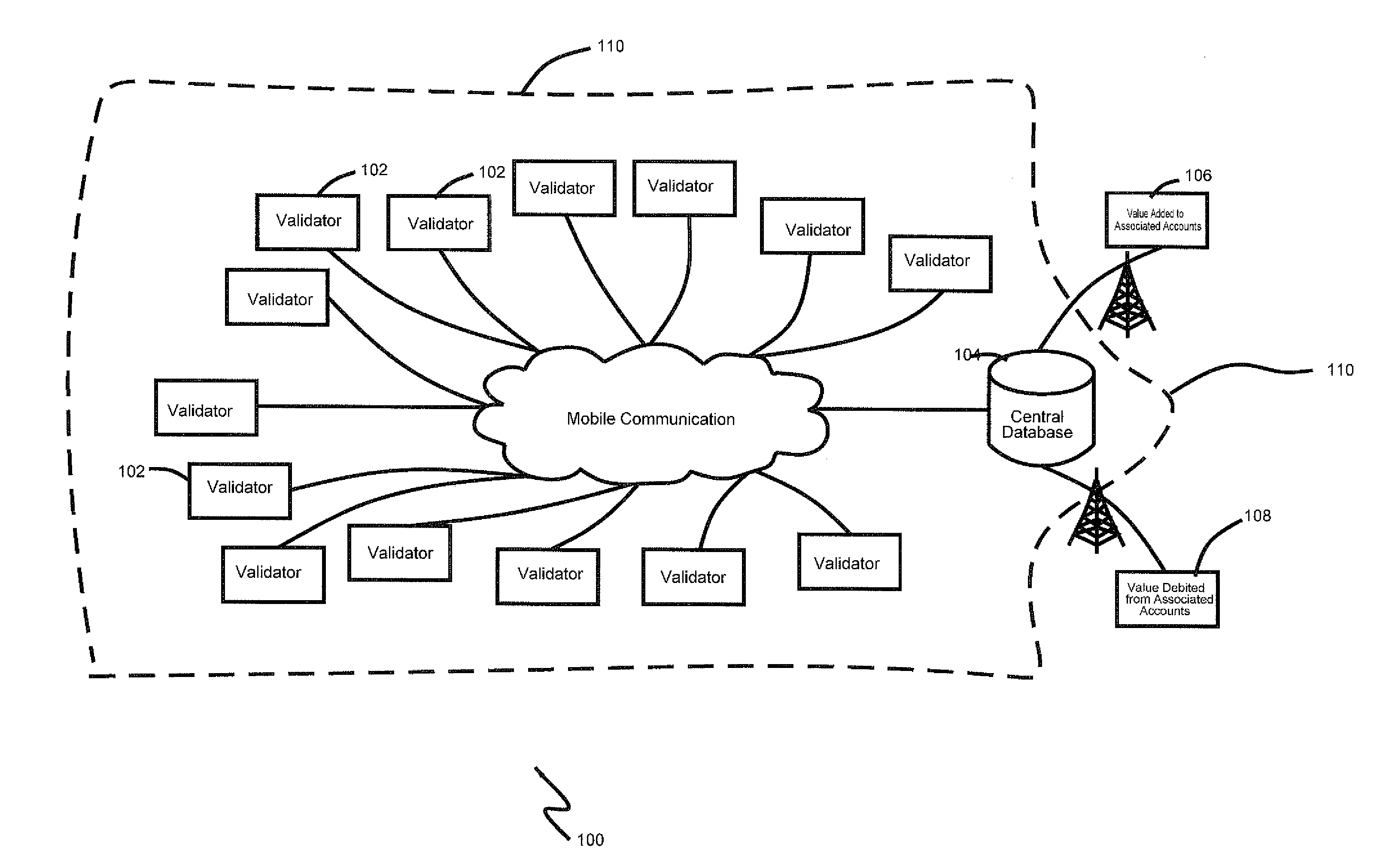
The invention is a system that links mobile money accounts, bank accounts, credit cards, and prepaid cards to fare cards and validators. This allows for real-time addition and tracking of usage of fare cards, with associated information collection and retrieval. The technical effect is a flexible and traceable system for managing and monitoring value transactions in real-time.

Problems solved by technology

Automated fare collection systems that do not allow stored-value fare cards force passengers to acquire fare cards whose monetary value is consumed or otherwise depleted, for example to a monetary value of zero, through usage and / or through the expiration of a time period.
Such systems place strain on associated transportation terminals, for example train station buildings, due to passenger congestion in the terminal building, on account of passengers waiting in line at card vending machines or booths to obtain fare cards or increase the monetary value of existing fare cards which have been depleted of value.
Likewise, these systems also burden passengers that must physically go to the card vending machines or booths and wait in line to obtain and / or increase the monetary or time value of fare cards every time that their previous fare cards are depleted of value.
The reason that certain automated fare collection systems do not allow stored-value fare cards is because stored-value fare card systems have higher launching costs in the case of new automated fare collection systems, and, in the case of pre-existing automated fare collection systems, high migration costs.

Method used


Image

  • Transit fare collection system
  • Transit fare collection system
  • Transit fare collection system

Examples


Embodiment Construction

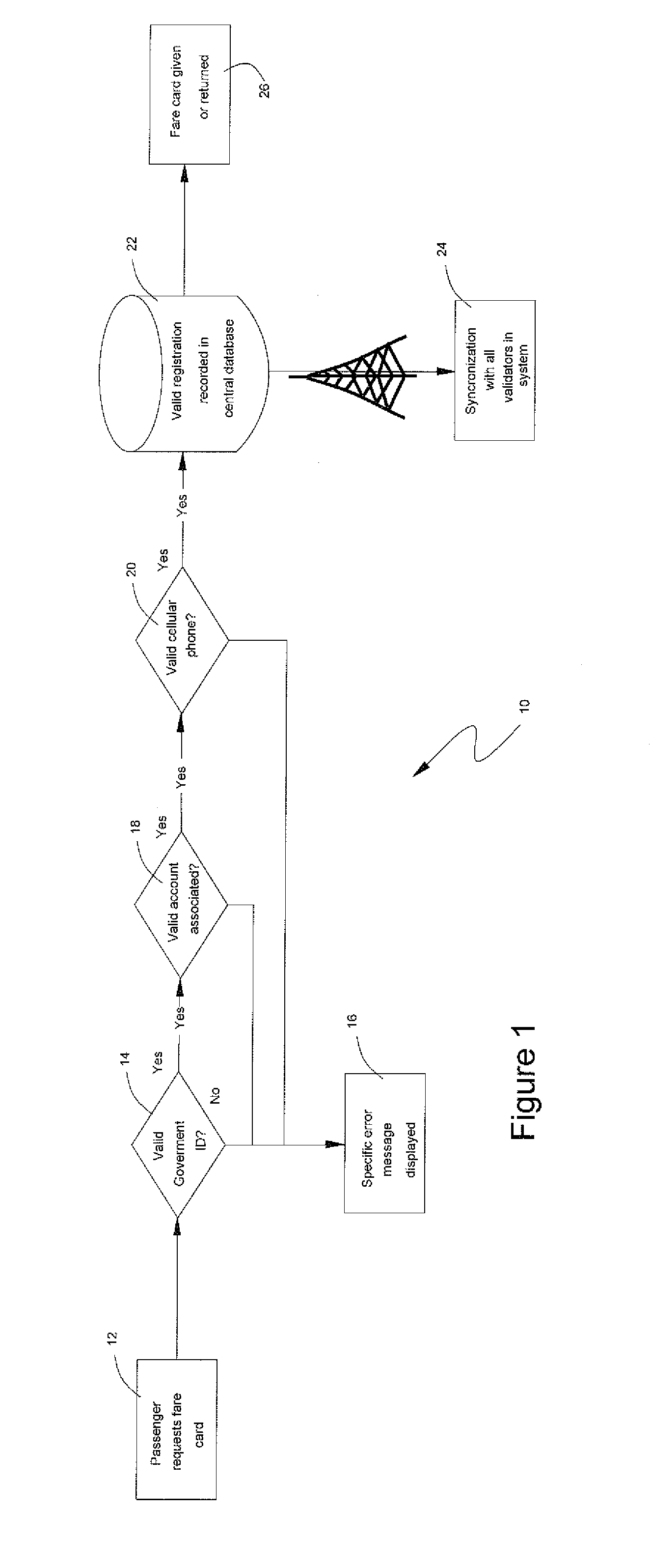
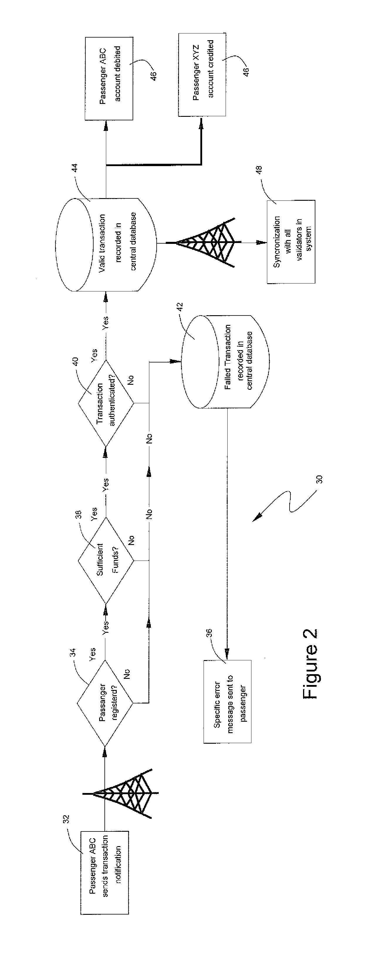
[0095]In accordance with the present invention, it is possible for a passenger to access funds from a mobile money account, bank account, credit card or prepaid card associated to a fare card in real time, without the need to visit an add value machine, with a cellular phone or on an internet site; or to receive value on his fare card account from any other person in real time, all as every validator and every fare card in the automated fare collection system is linked with the central database and all transactions are carried out therein in real time. Using the process illustrated in FIG. 1, a passenger ABC may obtain a fare card or register a pre-existing fare card and associate it to a mobile money account, bank account, credit card or prepaid card. In accordance with the preferred embodiment, passengers may associate their cellular phones and government issued identification to their fare card, however, neither is necessary for implementation of the invention.

[0096]While it is c...


PUM


Abstract

A method and apparatus for collecting transit fares is disclosed. The method implements databases contained within a central database that receive data indicating value. Detectable objects are associated with an identifier, which is then associated with one of the databases. Each identifier stores available fare value data in a database. Detectors that read the identifiers are placed at trip starting and / or endings locations and are coupled or couplable to a local memory that stores the identifiers and associated available fare data. Data sets from the central database comprising an available fare value and its associated identifier are downloaded on to the local memories from the databases. Once a detectable object is detected, its associated identifier is read and a fare is debited from the available fare value. The databases and local memories are periodically updated with updated fare values associated with each identifier.

Description

TECHNICAL FIELD[0001]The present invention relates to the field of computer-implemented automated fare collection systems in public transportation networks.STATEMENT REGARDING FEDERALLY SPONSORED RESEARCH OR DEVELOPMENT[0002](Not applicable)BACKGROUND OF THE INVENTION[0003]Many public transportation networks have introduced automated fare collection systems. Such methods involve automation of operator ticketing and collection systems with the objective of reducing costs by doing away with manual fare collection. Additional benefits include increasing efficiency in fare collection and associated procedures, and reducing fraud, for example that committed by passengers and public transportation network staff.[0004]Typically, a transit system includes a transit sector. Entry into the transit sector is blocked by turnstiles or other fare collecting systems, or another gatekeeper system. Such a transit system would also include entry areas which are freely accessible to the public without...

Claims


Application Information

Patent Timeline
IPC IPC(8): G07B15/06G07B15/04
CPCG07B15/04G07B15/06G07B15/02
Inventor MONTEALEGRE, HAROLDO
Owner MONTEALEGRE HAROLDO J
Learn More