Magnetic medium for magnetic encoder, magnetic encoder and method for manufacturing magnetic medium

Inactive Publication Date: 2015-04-30
HITACHI METALS LTD
View PDF7 Cites 4 Cited by
  • Summary
  • Abstract
  • Description
  • Claims
  • Application Information

AI Technical Summary

Benefits of technology

[0031]The present disclosure provides a magnetic medium, a magnetic encoder, and a method for manufacturing a magne

Problems solved by technology

The optical encoder is advantageously less likely to be affected by a peripheral magneti

Method used


Image

  • Magnetic medium for magnetic encoder, magnetic encoder and method for manufacturing magnetic medium
  • Magnetic medium for magnetic encoder, magnetic encoder and method for manufacturing magnetic medium
  • Magnetic medium for magnetic encoder, magnetic encoder and method for manufacturing magnetic medium

Examples


first embodiment

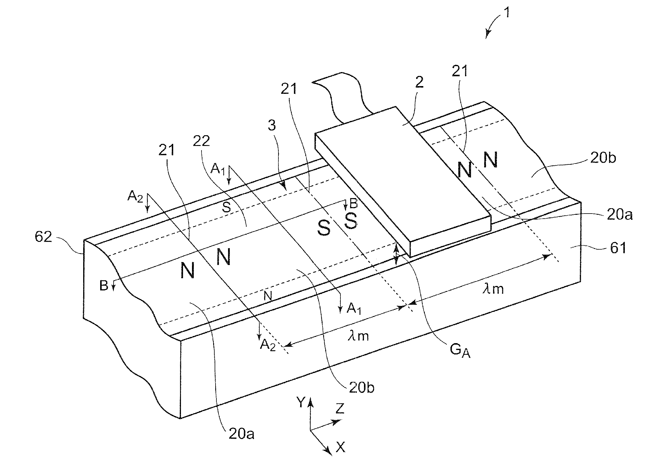
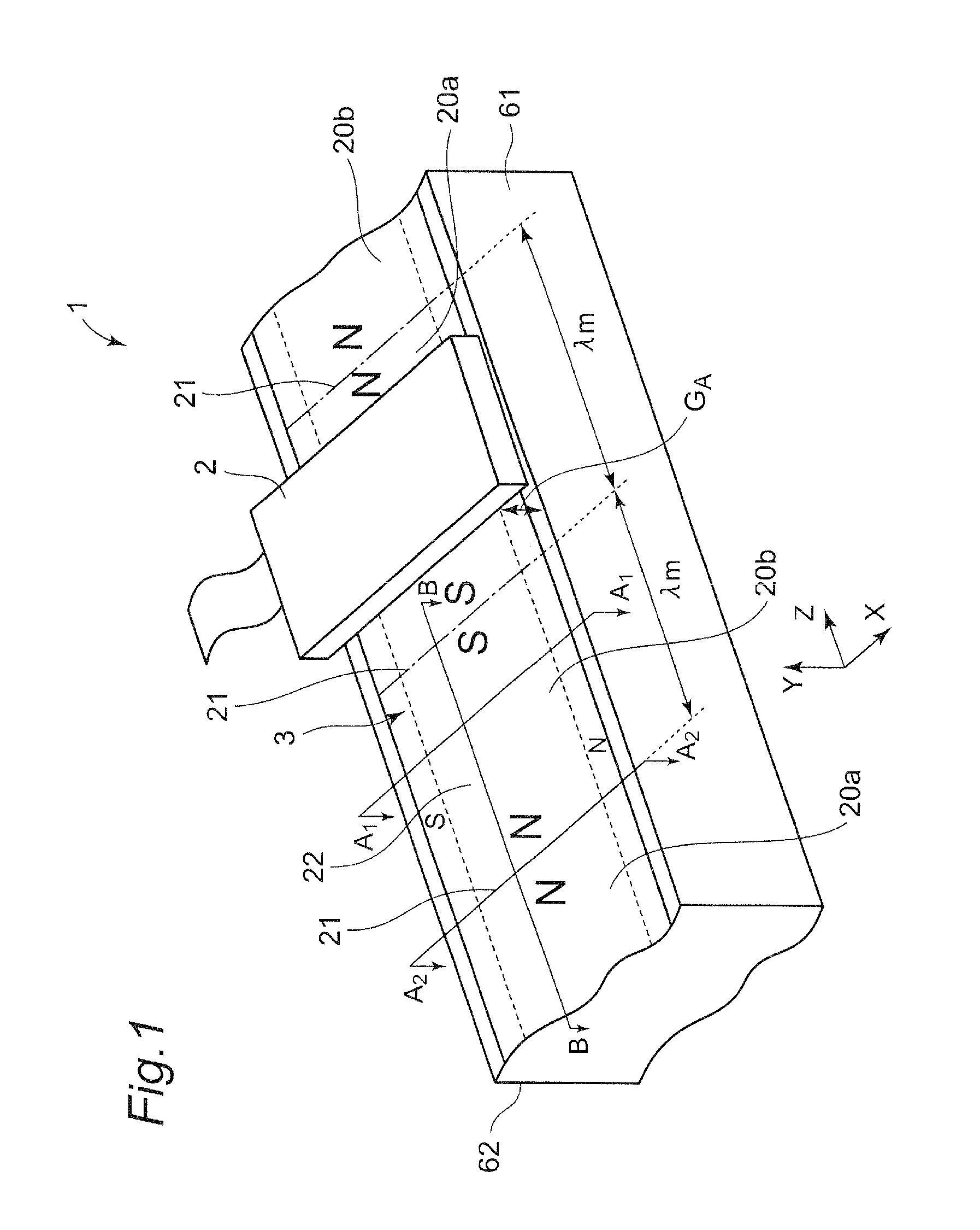
[0047]For better understanding of the present disclosure, first, the structure and function of a magnetic encoder including a magnetic sensor with a magnetoresistive effect element and a magnetic medium will be described below with reference to FIG. 1. The magnetic medium can be linearly provided to produce a linear type magnetic encoder. Alternatively, a ring-like magnetic medium can be provided over an outer peripheral surface of a drum in a ring-like shape to produce a drum magnetic encoder. Therefore, it is to be understood to those skilled in the art that the drum magnetic encoder can be implemented based on a specific example of the linear magnetic encoder below.

[0048]FIG. 1 is a schematic diagram of a linear magnetic encoder (hereinafter simply referred to as a “magnetic encoder or encoder”) 1 according to one embodiment of the present invention. As shown in FIG. 1, the linear magnetic encoder 1 of one embodiment of the present invention includes a magnetic sensor 2 with one ...

example 1

[0096]In a magnetic encoder 1 subjected to the bias magnetization and the signal magnetization according to the first embodiment of the present invention, the magnetic medium 3 was moved in each of the left and right directions with respect to the magnetic sensor 2 by 3 mm, and in the respective movements, outputs from the magnetic encoder 1 were measured. The result is shown in FIG. 3B.

example 2

[0097]In the magnetic encoder subjected to the bias magnetization and the signal magnetization in the first embodiment of the present invention, the air gap GA as a distance between the magnetic sensor and the magnetic medium was changed in a range from 50 μm to 400 μm to thereby determine the output amplitude (see FIG. 9) and accumulated error (see FIG. 10). The output amplitude is shown in FIG. 9 and the accumulated error is shown in FIG. 10.


PUM

PropertyMeasurementUnit
Magnetic fieldaaaaaaaaaa
Depthaaaaaaaaaa
Strengthaaaaaaaaaa

Abstract

The present disclosure provides a magnetic medium, a magnetic encoder, and a method for manufacturing a magnetic medium with high reliability that can obtain the sufficient signal output, while reducing the hysteresis error.
Disclosed is a magnetic medium relatively movable with respect to a magnetic sensor for detecting a magnetic field in a magnetosensitive face, the magnetic medium including: a signal magnetization region including a first magnetization region magnetized in a first direction being in parallel with the magnetosensitive face and a second magnetization region magnetized in a second direction opposed to the first direction, the first magnetization region and the second magnetization region being alternately arranged along the first direction or the second direction; and
    • a bias magnetization region magnetized in a third direction, the third direction intersecting both the first and second directions, and being in parallel with the magnetosensitive face, wherein
    • while a surface of the magnetic medium opposed to the magnetic sensor is placed to face upward,
    • the bias magnetization region is formed under the first magnetization region and the second magnetization region near an interface between the first magnetization region and the second magnetization region, and no bias magnetization regions are formed under the first magnetization region near a center of the first magnetization region and under the second magnetization region near a center of the second magnetization region.

Description

CROSS REFERENCE TO RELATED APPLICATIONS[0001]This patent application claims the benefit of priority from Japanese Patent Application No. 2013-223166 filed on Oct. 28, 2013, the entire contents of which are incorporated herein by reference thereto.BACKGROUND OF THE INVENTION[0002]1. Field of the Invention[0003]The present disclosure relates to a magnetic encoder for detecting a movement direction or movement amount of a moving member, or a rotation angle of a rotary body using a change in magnetism, a magnetic medium used for the magnetic encoder, and a method for manufacturing the same.[0004]2. Description of the Related Art[0005]Encoders are used in devices / apparatuses that require a precise control of the movement direction, movement amount, rotation angle, or the like.[0006]The encoders are mainly classified into an optical encoder and an electromagnetic induction encoder based on the principle of operation.[0007]The optical encoder is advantageously less likely to be affected by...

Claims


Application Information

Patent Timeline
IPC IPC(8): G01D5/16H01F41/00H01F13/00
CPCG01D5/16H01F41/00H01F13/00G01D5/2033Y10T29/4902
Inventor ABE, YASUNORIKAWAKAMI, MAKOTO
Owner HITACHI METALS LTD
Why Eureka
Try Eureka