Method For Trimming Carbon-Containing Film At Reduced Trimming Rate

a carbon-containing film and trimming rate technology, applied in the direction of electrical discharge tubes, basic electric elements, electrical apparatus, etc., can solve the problems of significant optimization of process conditions and non-uniform in-plane trimming rate, and achieve the effect of reducing trimming rate, effective reducing trimming rate, and improving the effective process margin of plasma generation

Active Publication Date: 2015-04-30
ASM IP HLDG BV
View PDF15 Cites 219 Cited by
  • Summary
  • Abstract
  • Description
  • Claims
  • Application Information

AI Technical Summary

Benefits of technology

[0008]In some embodiments of the present invention which resolve at least one of the problems, various methods to effectively reduce trimming rate are provided. In some embodiments, nitrogen gas is added to a trimming gas, and / or RF power is switched on and off at high speed to form a pulse train of RF power, thereby reducing trimming rate while improving effective process margin of plasma generation and in-plane uniformity of trimming rate. In some embodiments, trimming rate can be reduced to 60 nm / min or less, preferably 55 nm / min or less, more preferably 50 nm / min or less, without plasma ignition failure or other defects.

Problems solved by technology

However, when RF power is too low, problems occur, e.g., generation of plasma becomes unstable, and in-plane plasma distribution becomes uneven, resulting in non-uniform in-plane trimming rate.
However, because optimal hardware required for these two processes is different, optimization of process conditions for the processes is a significant problem.

Method used


Image

  • Method For Trimming Carbon-Containing Film At Reduced Trimming Rate
  • Method For Trimming Carbon-Containing Film At Reduced Trimming Rate
  • Method For Trimming Carbon-Containing Film At Reduced Trimming Rate

Examples


examples 1 to 6

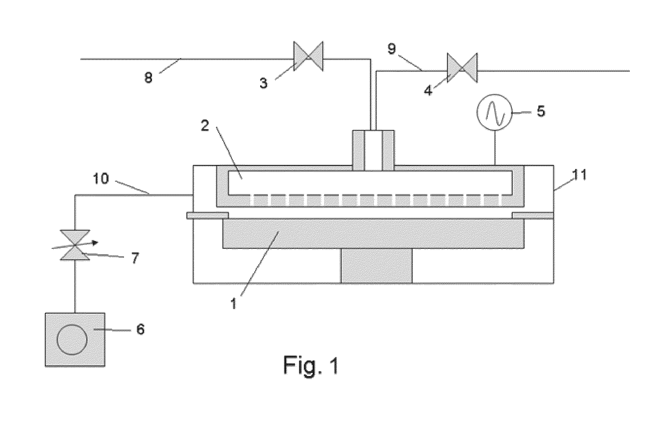
[0077]A 300-mm substrate having a patterned photoresist having an aspect ratio of about 2 and an opening width of about 50 nm was provided. The substrate was subjected to trimming under conditions shown in Table 1 below using the sequence illustrated in FIG. 3 and a plasma-processing apparatus similar to that illustrated in FIG. 1, which was a module having dual reaction chambers. In Table 1 (and also the other tables), items (1) to (15) represent the following:

[0078](1) RF power for trimming [W] (13.56 MHz)

[0079](2) Oxygen flow rate for trimming [sccm]

[0080](3) Nitrogen or carbon dioxide flow rate for trimming [sccm]

[0081](4) Reaction chamber pressure [Pa]

[0082](5) Distance between electrodes [mm]

[0083](6) Temperature of the substrate [° C.]

[0084](7) Temperature of pre-baking [° C.]

[0085](8) Duration of pre-baking [seconds]

[0086](9) Duration of oxygen-free RF power [seconds]

[0087](10) Oxygen-free RF power [W] (applied in step 1 of FIG. 3)

[0088](11) Duration of oxygen-free transitio...

examples 7 to 10

[0095]Examples 7 to 10 were conducted in a manner substantially similar to that in Examples 1 to 6 under conditions shown in Table 2 below.

TABLE 2Ex.(1)(2)(3)(4)(5) (6)(7)(8) (9)(10)(11)(12)(13)(14)(15)7606000 N2: 0 200 1375——0.51500.160—8Ar: 5008601000 N2: 2000200 1375——0.51500.160—8Ar: 5009601000 N2: 4000200 1375——0.51500.160—8Ar: 50010601000 N2: 6000200 1375——0.51500.160—8Ar: 500

[0096]The results are shown in FIG. 8. FIG. 8 is a graph showing the relationship between trimming rate [nm / min] and nitrogen flow rate [sccm] according to Examples 7 to 10. As shown in FIG. 8, by adding nitrogen gas to oxygen gas as a trimming gas, the trimming rate can be reduced significantly. Further, in-plane trimming uniformity was determined, and the results are shown in FIG. 18. FIG. 18 illustrates results of changing trimming gas compositions according to Examples 7 to 10. In the figure, “Thick.Ave.” refers to the average trimmed (reduced) amount in thickness of the film (measured at 49 locations...

examples 11 to 14

[0097]Examples 11 to 14 were conducted in a manner substantially similar to that in Examples 1 to 6 under conditions shown in Table 3 below. In these examples, RF power was turned off and on at a cycle of ⅕,000 seconds.

TABLE 3Ex.(1)(2)(3)(4) (5)(6) (7)(8)(9)(10)(11)(12)(13)(14)(15)11606000—2001375——0.51500.160258Ar: 50012 606000—200 1375——0.5150 0.160508Ar: 50013606000—2001375——0.51500.160808Ar: 50014 606000—200 1375——0.5150 0.160100 8Ar: 500

[0098]The results are shown in FIG. 9. FIG. 9 is a graph showing the relationship between trimming rate [nm / min] and duty cycle of RF power [%] according to Examples 11 to 14. As shown in FIG. 9, when RF power was applied in pulses, by reducing the duty cycle, the trimming rate can be reduced significantly. Further, in-plane trimming uniformity was determined in the same manner as in FIG. 18, and the results are shown in FIG. 19. FIG. 19 illustrates results of changing duty cycles of RF power according to Examples 11 to 14. As shown in FIG. 19, ...


PUM


Abstract

A method for trimming a carbon-containing film includes: (i) providing a substrate having a carbon-containing film formed thereon; (ii) supplying a trimming gas and a rare gas to the reaction space, which trimming gas includes an oxygen-containing gas; and (iii) applying RF power between the electrodes to generate a plasma using the trimming gas and the rare gas and to thereby trim the carbon-containing film while controlling a trimming rate at 55 nm/min or less as a function of at least one parameter selected from the group consisting of a flow rate of an oxygen-containing gas, a flow rate of nitrogen-containing gas to be added to the oxygen-containing gas, pressure in the reaction space, RF power, a duty cycle of RF power, a distance between the electrodes, and a temperature of a susceptor on which the substrate is placed.

Description

BACKGROUND OF THE INVENTION[0001]1. Field of the Invention[0002]The present invention generally relates to a method for trimming a carbon-containing film such as a photoresist at a reduced trimming speed, for spacer-defined double patterning (SDDP), for example.[0003]2. Description of the Related Art[0004]In semiconductor manufacturing processes, fine patterns for circuits, for example, are formed on a semiconductor wafer by etching such as plasma-assisted etching. Recently, formation of finer patterns has progressed by using spacer technology. As an example of such technology, spacer-defined double patterning (SDDP) is explained below. In the SDDP process, patterns are formed as core materials using photoresist or spin-on-carbon (SOC) at intervals which correspond to resolution limit, and then sidewall spacers are formed on sidewalls of the core materials. Thereafter, the core materials are removed while maintaining the sidewall spacers, and the remaining sidewall spacers are used ...

Claims


Application Information

Patent Timeline
Patent Type & Authority Applications(United States)
IPC IPC(8): H01L21/027H01L21/3065
CPCH01L21/3065H01L21/0273H01J37/32091H01J37/32146H01L21/0337H01L21/31138
Inventor ISII, YOSHIHIRONAKANO, RYUINOUE, NAOKI
Owner ASM IP HLDG BV
Why Eureka
Try Eureka